Microfluidics for Cell Biology
The Advantages of Flow Control for Cell biology and Microscopy
- Shear stress control
- Automation of multiple fluid delivery
- Long term perfusion
What are the advantages of microfluidics in biology?
The development of microfluidics has brought many advantages for biological research. Indeed, due to the miniaturization and the automation of the setups, the consumption of sample and reagent is largely decreased, the experiment times are considerably reduced and the global costs of the applications are minimized. Moreover, working with small quantities allows better carry out separations and detection with high resolution and sensitivity at reduced costs.
Finally, thanks to this new generation of techniques and equipments, new capabilities are offered for biology research since microfluidics allows to obtain more accurate results, to reduce detection limits and even to perform multiple analyses simultaneously.
To learn more about it, feel free to reed our white paper about microfluidic.
Main applications of microfluidics in cell biology

RNA and DNA Hybridization
For decades, in situ hybridization has been used with greater frequency to capture the localization, structure and expression of specific DNA and RNA sequences within tissues. The high sensitivity and specificity of this technique relies on the hybridization of labelled oligonucleotide probes to targeted DNA or RNA sequences within tissues. Chromosomal microdeletion, amplification, structure, translocation and expression can be easily detected.
Compared to PCR analysis, Northern Blotting or a DNA microarray performed on lysed cells, hybridization provides spatial information as specific RNA and DNA are detected within tissues. It has significantly improved gene mapping, cytogenetics and various diagnostic techniques (oncogenic, prenatal, viral infection, etc.).
Recently, with the use of microfluidic for cell biology, a temporal dimension was added to the technology, as it further evolved to be performed on living cells. The spatio-temporal expression, degradation and storage of RNA molecules can now be thoroughly investigated by real time imaging of the hybridization of labelled oligonucleotides in living cells.

Drug Combination and Long-Term Perfusion
In various therapeutic areas (glaucoma, vascular, HIV, oncology), a combination of drugs is typically found to be more effective for disease treatment. Oncology, in particular, has paved the way for this approach. The emergence of next-generation sequencing technology profiling has revealed the heterogeneity in many cancers at the origin of the differential response to treatment. As a result, therapeutic strategies are evolving towards multi-targeted drug combinations that effectively inhibit the cancer cells and block the emergence of drug resistance while selectively incurring minimal side effects on healthy cells.
Drug combination therapy is not straight forward as in many cases the results do not equal the sum of the parts. Cross-reactions are observed and fall into 5 categories: low risk & synergy, low risk & no synergy, caution, unsafe, and dangerous. The contribution and dosage of each active molecule should be closely investigated in terms of dose, frequency and duration to evaluate the efficacy of the drug combination.
Therefore, microfluidics for cell biology holds great promise in cancer diagnosis and also serves as an emerging tool for understanding cancer biology. Microfluidics can be a valuable tool in cancer investigation due to its high sensitivity, high throughput, less material-consumption, low cost, and enhanced spatio-temporal control.

Immunostaining
Immunostaining experiments are mult-istep protocols to detect specific antigens in biological samples. The sample is successively incubated or exposed to fixation agents, washing buffers, and probes.
In conventional protocols on petri dishes or well plates, fluid deliveries are performed manually using pipettes. Solutions are directly added to the sample.
Transferring protocols from a Petri dish to a microfluidic format usually requires some minor adjustments, as cells or tissue samples are exposed to solutions differently. Therefore, the use of microfluidic for cell biology provides many advantages by replacing the use of Petri dishes with microfluidic chambers (closed systems). Consequently, solutions cannot be deposited directly on the top of the cells but are perfused over the sample at a controlled flow rate, reaching all cells homogeneously. The use of a rotary valve with a perfusion system enables one to perfuse different solutions at given time points in the chip or chamber. In addition, automating the sequential delivery of solutions saves time and avoids creating bubbles inside the chips by disconnecting and reconnecting the traditional pump to the chip.
Resources
-
Microfluidics case studies CNRS/UTC: study of a liver-on-a-chip model Read more
-
Expert Reviews: Basics of Microfluidics Why is a controlled shear-stress a key parameter of your microfluidic experiments? Read more
-
Microfluidic Application Notes Cancer Cell Analysis Made Easy with Aria: cell Capture and Labeling Read more
-
Microfluidic Application Notes Peristaltic Pump vs Pressure-Based Microfluidic Flow Control for Organ on Chip applications Read more
How important is the microlfluidic flow control in cell biology?
In drug discovery, it‘s important to control the flow rate of the sample used. As multiple formulations are tested, experimenters must be able to control flow rate while keeping the same level control of fluid handling at each stage of the experiment. DNA and RNA hybridization are often performed under a microscope. Manual injection over a microscope can be risky for the following reasons:
- A touch of pipette cone can misplace the dish and misrecord the position
- Samples can be flushed away during pipetting
- Liquid can be spilled over the microscope
Flow Controllers Available on the Market
Syringe Pumps
Multiple flow control technologies are available for sub-millimeter range fluid management. Syringe pumps are commonly used for fluid control. However, in microfluidics, particularly in microfluidics for cell biology, the use of syringe pumps is often problematic because the flow is not constant. This discontinuity is due to the mechanical system that creates an oscillating flow.
Manual Injection
Current methods for multiple fluid delivery, where microscopy techniques are simultaneously required and mostly made by manual pipetting action include , Immunolabeling, and DNA and RNA hybridization.. Manual injection can lead to uncontrolled and non-homogeneous fluid velocity, which can damage samples.
| Pipette | Aria | |
|---|---|---|
| Type of injections | Abrupt injections (up to 1mL in few seconds) Disparate injections Turbulent flow | Smooth & controled injections Identical injections Laminar flow |
| Geometry at injecion tip | Conic shape: Important shear strain Unhomogeneous fluid velocity | Straight shape: No modification at the injection tip |
Fluigent Pressure-Based Flow Control
As the demand for microfluidic pumps with higher flow stability, fast response time, versatility, and automation capabilities has increased, pressure controllers have become the device of choice for many users.
The working principle of such pumps is to pressurize the sample reservoirs to control the pressure drop between the inlet and the outlet of the microfluidic system. The responsiveness of the generated flow rate depends on the responsiveness of the pressure pump.
To overcome these issues, Fluigent’s Aria automates multiple fluid deliveries. The sample is preserved as the flow rate is controlled. Reproducibility increases as inter and intra operator variability are eliminated.

A new level of technology
Microscopy and cell biology
Flow cells or microfluidic chips combined with a fluid perfusion system and microscopy are compatible with a variety of applications, including DNA and RNA hybridization, drug combination and long-term perfusion, and immunostaining.
Cell culture and Organ-on-a-chip
This area is an ideal microenvironment to study molecular and cellular-scale activities that underlie human organ function as well as identify new therapeutic targets in vitro.
Digital PCR
Microfluidic dPCR offers a new level of insight compared to quantitative PCR (qPCR). Droplet-based microfluidics is an excellent solution for partitioning a sample.
Want to learn more about the capabilities of microfluidics in life science? See Fluigent’s CEO France Hamber discuss microfluidic disruptive discoveries
Research applications


Microfluidics in biology and medicine
Microfluidics has emerged as a transformative technology, revolutionizing various areas of research, diagnostics, and therapeutics. By enabling precise manipulation and control of small volumes of fluids at the microscale level, microfluidic devices, also known as lab-on-a-chip, have opened up new possibilities in the study of cells, diagnostics, DNA sequencing, and drug discovery. In biology, microfluidics allows researchers to analyze and manipulate individual cells, paving the way for advancements in cell biology and single-cell genomics. In medicine, microfluidic platforms offer portable, rapid, and cost-effective point-of-care diagnostics, bringing healthcare to resource-limited settings, e.g. by using organ-on-chip platforms.
As an example, microfluidics in life science has accelerated RNA sequencing technologies, enabling high-throughput sequencing at reduced costs. In the application note linked below, Fluigent presents the Drop-Seq method, a high-throughput method that enables sequencing of the mRNA from a large number of cells. The Drop-Seq method pairs barcoded beads and cells in droplets, capturing cell-specific RNA on beads. Tagged cDNA is generated, amplified, sequenced, and bioinformatically analyzed. Barcode sequences identify cells, and transcript sequences are mapped to a reference genome, forming cell-specific gene-expression profiles.
Microfluidic tools for cell biological research
Cellular biology plays a crucial role in the field of medical science and drives innovation. A comprehensive understanding of how cells react during infections and pathological conditions is instrumental in the discovery of novel disease treatments. Essential to the analysis and visualization of cellular behavior are microscopy and imaging technologies. In the realm of cell biology, the integration of precise fluid flow control within microfluidic systems has revolutionized the study of cells by providing an automated platform that mimics their natural environment.
Microfluidics facilitates the delivery of fluids at controlled flow rates, minimizing errors. It finds applications in diverse areas such as RNA and DNA hybridization, enabling real-time imaging of gene expression in living cells. Microfluidics also contributes to drug combination therapies, long-term perfusion studies, and improved immunostaining protocols. By replacing traditional methods, microfluidics in life science offers several advantages including enhanced control, sensitivity, throughput, cost-effectiveness, and reduced material consumption. Its potential impact extends to cancer diagnosis, enhancing our understanding of cancer biology, and driving advancements in medical research.
Advantages of pressure-based flow controllers for life science experiments
Pressure-based flow controllers offer several advantages over peristaltic pumps and syringe pumps in microfluidics for life science applications. Firstly, it provides precise and accurate control of flow rates, allowing for better reproducibility and control of experimental conditions. Secondly, the pressure-based system is less prone to pulsations and variations in flow, resulting in more stable and consistent flow profiles. Additionally, using pressure-based controllers in life sciences allows researchers to work with much smaller volumes, which is useful when the samples to be studied are expensive or rare.
Finally, using pumps like the Flow EZ allows for use of various accessories such as reservoir mixers or block heaters, which can reproduce the physiological conditions of cells, for example, and keep the sample homogeneous, which is much more complex, if not impossible, with other types of pumps.
Organ-on-chip studies for life science
Organs-on-chips (OoC) are microdevices that mimic organ functions. They use microfluidics and 3D culture to replicate human physiology. OoC models show that dynamic culture conditions affect system maturation. They aim to recreate tissue barriers, parenchymal tissues, and inter-organ interactions. An OoC system includes a microfluidic chip with cell culture chambers, fluid channels, and optional components like membranes or gels. Biosensors and bio-actuators may be added. This technology is very useful for microfluidics in life science applications, as it offers more realistic lab modeling of organs and tissues. To that end, Fluigent has created Omi, a versatile and automated platform for organ-on-chip studies.
Omi allows for long-term cell culture with controlled shear stress conditions through continuous flow. It offers customizable and automated protocols for various functions, such as perfusion, recirculation, sampling and injection. This platform caters to the requirements of both novice cell culture researchers and experienced organ-on-chip researchers, addressing their needs for automation and reproducibility.
Microfluidic in Life Science Case Study
Hans-Knöll-Institut, New Antibiotics, Cultivation in Droplets
This project focuses on how Fluigent’s customers use microfluidics to achieve outstanding results in their technology experiments.
Our speakers are Prof. Dr. Miriam Agler-Rosenbaum (Head of Bio Pilot Plant Department), Dr. Sundar Hengoju, Dr. Dede Man from the Bio Pilot Plant Department of the Leibniz Institut for Natural Products Research and Infection Biology (Hans Knöll Institute).
- How are they trying to find new antibiotics?
- Why is this important for infection biology?
- How do they research natural products?
- What are these products exactly?
- How does microfluidics allow them to cultivate microbes in droplets?
- How does the technology increase their efficiency millions of times over?
- In which cases are pressure pumps better than syringe pumps?
- How can microfluidic droplets be stabilized?
Watch this episode to find out – and note that this is just one story told. There are many possible applications for microfluidics.
Related products
Research field
Fluid Degassing Device for Microfluidic System
Microfluidic Fluid Degassing Device
See the offer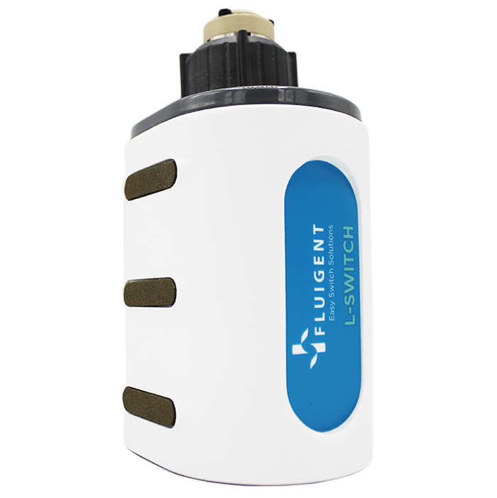
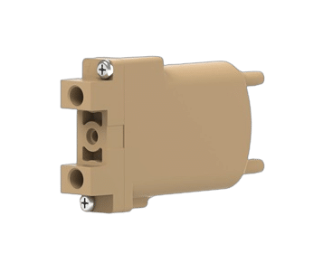
Microfluidic Injection Valve
L-SWITCH™ 6-port/2-position
See the offer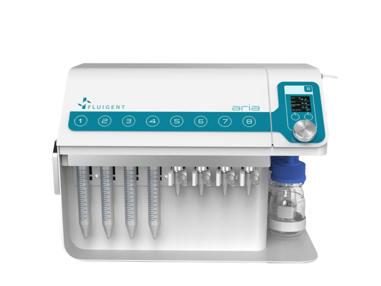
Automated Perfusion System for Spatial Omics
Aria
See the offer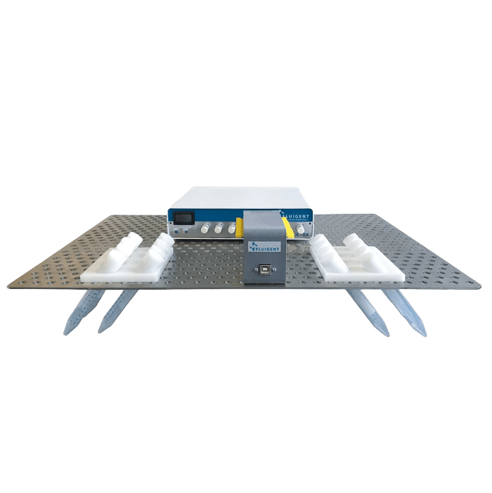
High Throughput Cell Perfusion Pack
High Throughput Cell Perfusion Pack
See the offer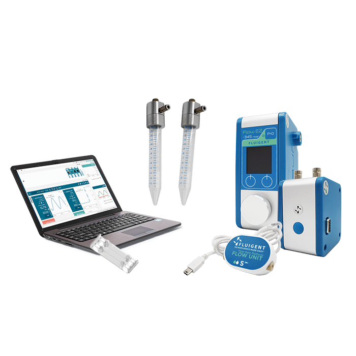
Organ on Chip Perfusion Pack
Perfect organ-on-chip cell perfusion set
See the offer
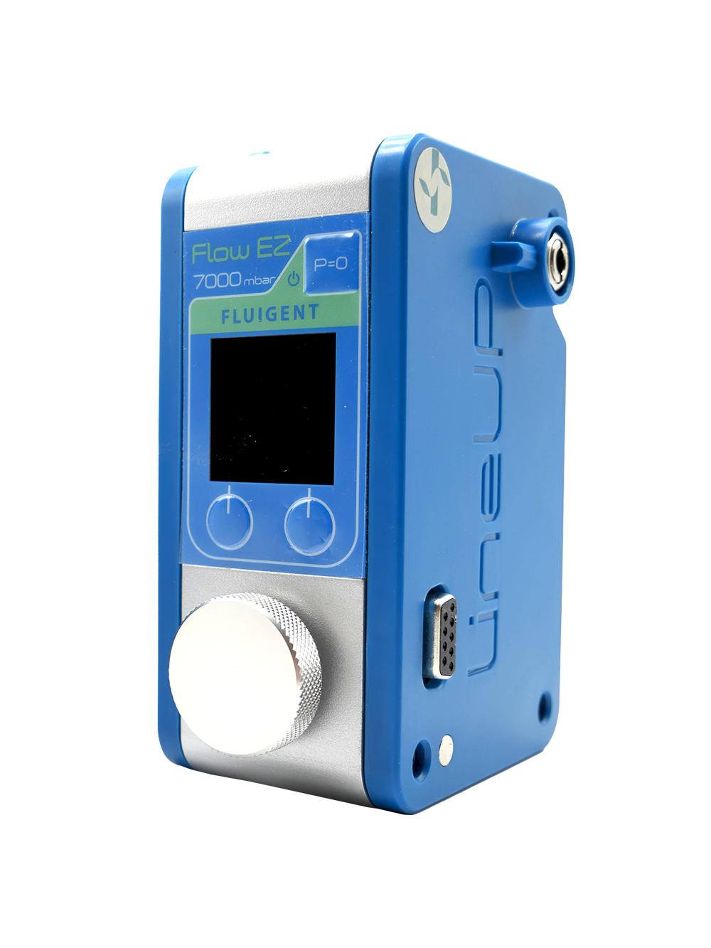
Microfluidic flow controller
Flow EZ™
See the offer-
Microfluidic Recirculation Valve
L-SWITCH™ 6-port/2-position
See the offer 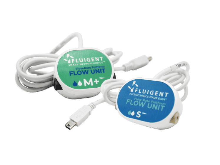
Bidirectional Microfluidic Flow Sensor
FLOW UNIT | FLOW UNIT +
See the offer
Microfluidic reservoir block heater
Heat fluid reservoirs during your microfluidic experiment
See the offer


Industrial field


Related Expertises


Looking for another market?
From the life sciences to the food industry, many applications require the use of fluids driven at flow rates from nanoliters to milliliters per minute. At such low flows, the success of these applications strongly depends on the level of control and automation of the fluidic operations.
These applications require flow control systems that are adapted for ensuring their success.
About The Keyser lab – University of Cambridge
The Keyser Lab is a group of researchers at the Cavendish Laboratory, University of Cambridge, UK. Since its founding in 1874, the Cavendish Laboratory has been at the forefront of discovery in physics, with a core focus on experimental physics supported by excellence in theory. The department promotes world-leading experimental and theoretical physics in all its diversity. Scientists from the Keyser Lab study the physics of ions, macromolecules and particles, with a particular focus on particles in confined geometries at the single molecule/particle level. To exert maximum control over all parameters for their experiments, they make use of several cutting-edge techniques such as DNA self-assembly (origami), optical trapping, electrophysiology, and microfluidics and nanofluidics.
The team includes researchers with expertise in physics, engineering, physical chemistry, biochemistry/biology, and micro- and nanofabrication.
What are Giant Unilamellar Vesicles (GUVs)?
Giant Unilamellar Vesicles (GUVs) are micron-sized compartments composed of lipid bilayers, serving as models for cell membranes or as encapsulating structures for biological materials within cell-like environments. These vesicles have dimensions ranging from 1 to 100 µm, mimicking the size of cells. Like natural cell membranes, GUVs are constructed from lipids, predominantly phospholipids and cholesterol. The amphiphilic properties of these lipids enable them to spontaneously arrange into spherical compartments when immersed in an aqueous solution.
They offer the advantages of having well-defined lipid compositions, being easy to image, and being controlled systems for studying transport processes. These characteristics open the door to a variety of applications in biology and biomedicine, especially membrane biophysics and synthetic biology.1,2

Working principle of GUV production

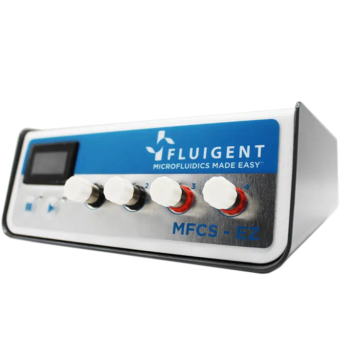
In 2016, the Dekker Laboratory from the Delft University of Technology developed a novel microfluidics-based method called Octanol-Assisted Liposome Assembly (OLA) to create uniform, cell-sized (5–20 mm) GUVs with high encapsulation efficiency. Using Fluigent’s pressure-driven MFCS-EZ controller with the Oxygen software tool, an inner aqueous phase (IA) and an outer lipid-carrying 1-octanol phase (LO) were combined, resulting in double-emulsion droplets via hydrodynamic flow focusing. These droplets developed a side-connected 1-octanol pocket, which, due to interfacial energy minimization, separated to rapidly form fully assembled solvent-free liposomes. Microfluidic GUV production addresses the persistent issue of residual oil in vesicle bilayers.
This method allows researchers to generate GUVs with higher monodispersity and greater size control compared to traditional methods, and with a faster process than alternative microfluidic methods.3


Keyser Lab: Microfluidics for GUV generation for antimicrobial efficacy and biomimetic vesicle membrane testing
Scientists from the University of Cambridge integrated octanol-assisted liposome assembly into their microfluidic platforms (“lab on a chip” devices) for quantifying drug permeation and antimicrobial efficacy on biomimetic vesicle membranes.
In a first paper published in Lab on a Chip (2019), they reported on a microfluidic platform for testing antimicrobial peptides on artificial vesicle membranes. This platform produced vesicles with an encapsulated dye to assess the efficacy of antimicrobial peptides by measuring the time it takes for vesicles to lyse.4
This Giant Unilamellar Vesicle production technique also utilized Fluigent‘s MFCS-EZ and its accompanying software (Oxygen) for fluid control. Vesicle formation and perfusion inlets were connected, and the microfluidic chip was loaded with an inner aqueous phase base stock. The outlet was connected to Fluigent’s 2-Switch, which can switch between open or closed configurations for waste removal. Vesicles flowed through a channel to the connector chip, and 1-octanol pockets pinched off to form droplets. Density-based separation removed vesicle production waste, and the vesicles were distributed to trapping chambers. Peptide doses were controlled, replacing the inner aqueous phase buffer, while maintaining a constant input pressure. The entire process was monitored under an inverted microscope.
Validated with cecropin B on bacterial-mimicking membranes, the platform enabled the researchers to study over 1000 vesicles simultaneously. The results showed dose-dependent disruption of vesicle membranes, demonstrating the platform’s potential for controlled, quantitative assessments of the efficacy and selectivity of antimicrobial peptides. This microfluidic approach to GUV production is suggested as a new standard for pre-clinical development of membrane-active antimicrobials, offering advantages in cost efficiency and parallelization.


In another paper published in Biomembranes (2020), scientists from the University of Cambridge and the University of Exeter produced GUVs with tunable binary lipid mixtures to determine lipid diffusion in OLA vesicles.5
The focus was on expanding the capabilities of this microfluidic approach to form GUVs with tunable binary lipid mixtures. An MFCS-EZ equipped with a Fluiwell-4C reservoir kit with OLA solutions was connected to the microfluidic chip. The microfluidic GUV production method allowed for a high degree of control over vesicle sizes by adjusting pressures in different channels. This was possible due to the high responsiveness, stability and repeatability of the pressure generated by the MFCS-EZ. In addition, flow speed was successfully matched to the outlet channel length to prevent residual octanol attachment to vesicles.
This study employed fluorescence recovery after photobleaching to investigate lipid lateral diffusion coefficients in GUVs produced by the microfluidic approach, finding values within the expected range. Comparisons with electroformed vesicles indicated quantitative similarity in lipid diffusion coefficients. The results served as a quantitative biophysical validation of OLA-derived GUVs, enhancing the potential application of this versatile platform in drug discovery, artificial cell production, and lipid membrane studies.


Conclusion
To produce Giant Unilamellar Vesicles, fluids were controlled using Fluigent pressure-based flow controllers. Researchers from the Keyser Lab (University of Cambridge) typically operated the chip with input pressures of 40 mbar for the inner aqueous phase and dissolved-lipid phases and 100 mbar for the outer aqueous phase. For precise flow measurements, Fluigent Flow Units can be added on the fluidic path. Microfluidic GUV production also allowed researchers to adjust the sizes of the generated vesicles by adjusting the microfluidic pressures of the phases. This degree of control is difficult to achieve using standard methods such as electroformation or traditional syringe pumps.
Testimonials

“Microfluidics presents various advantages to researchers who need small volumes and high throughput in answering their scientific questions. In our lab, we use microfluidic devices for standardization and control of experimental parameters like concentration and timing. In the complex (biological) systems we are working on, the mentioned characteristics are fundamental in collecting reliable meaningful statistics, and microfluidics in combination with light microscopy offers just that. We also heavily rely on the ability to rapidly prototype devices, as we can design bespoke solutions at minimal production cost and time.”
“We use the pressure-based pumps from Fluigent for experiments that require swift responsiveness when manipulating fluids, and fine tuning at low flow rates. We use the Fluigent systems during fabrication and running of the microfluidic chips. The ability to pump in air at high precision makes the Fluigent pressure-based systems ideally suited to selectively coat and functionalize micro-channels within a microfluidic network. After coating we then fill the devices with the experimental solutions and use the pressure controls to move fluids around, open and close valves and carefully time the introduction of small molecules in the experiments.“
Kareem Al Nahas, University of Cambridge
Expertises & Resources
-
Expert Reviews: Basics of Microfluidics Giant Unilamellar Vesicles (GUVs) Production using Microfluidics Read more
-
Microfluidics Article Reviews A mRNA encapsulation platform integrating Fluigent’s FlowEZ Read more
-
Expert Reviews: Basics of Microfluidics Microfluidics for vaccine development Read more
-
Microfluidic Application Notes Liposome Nanoparticle Synthesis Read more
-
Expert Reviews: Basics of Microfluidics Flow control for droplet generation using syringe pumps and pressure-based flow controllers Read more
References
- Naziris, N., Demetzos, C. (2021). Liposomes: Production Methods and Application in Alzheimer’s Disease. In: Vlamos, P. (eds) GeNeDis 2020. Advances in Experimental Medicine and Biology, vol 1339. Springer, Cham.
- Pereira, David & Valentão, Patrícia & Andrade, Paula. (2014). Nano- and Microdelivery Systems for Marine Bioactive Lipids. Marine Drugs. 12. 6014. 10.3390/md12126014.
- Deshpande, S.; Caspi, Y.; Meijering, A. E. C.; Dekker, C. Octanol-Assisted Liposome Assembly on Chip. Nat Commun 2016, 7 (1), 10447.
- Al Nahas, K.; Cama, J.; Schaich, M.; Hammond, K.; Deshpande, S.; Dekker, C.; Ryadnov, M. G.; Keyser, U. F. A Microfluidic Platform for the Characterisation of Membrane Active Antimicrobials. Lab Chip 2019, 19 (5), 837–844.
- Schaich, M.; Sobota, D.; Sleath, H.; Cama, J.; Keyser, U. F. Characterization of Lipid Composition and Diffusivity in OLA Generated Vesicles. Biochimica et Biophysica Acta (BBA) – Biomembranes 2020, 1862 (9), 183359.
Microfluidic chip definition
Microfluidic chips, often referred to as lab-on-a-chip devices, are miniature platforms that manipulate and analyze small volumes of fluids. These chips, witch feature molded or patterned micro-channels, integrate various functions, such as mixing, pumping, and sensing, onto a compact substrate, enabling precise control over minute amounts of liquids.
Inlet and outlet ports connect this network to the external environment. Liquids or gases can be injected, managed, and removed from the microfluidic chip through passive or active methods, wich may involve pressure/flow controllers, syringe pumps, or peristaltic pumps. The microscale fluidic chip’s channels may have varying inner diameters, typically ranging from 5 to 500 µm, but today’s fabrication techniques enable structures with sub-micrometer precision.
The channel network must be specifically designed for the desired application and analysis (cell culture, organ-on-a-chip, DNA analysis, lab-on-a-chip, microfluidic droplets, etc.).
A Brief History of Microlfuidic Chips
The roots of microfluidics trace back to the mid-20th century. However, it was in the late 20th and early 21st centuries that the field truly blossomed.
Miniaturization techniques have been continuously shaping the microelectronic’s technology and its ability to produce devices for a broad range of applications. Downscaling the dimensions of transistors has been pursued in the industry to fulfill the growing demand for smaller, faster and more energy-efficient systems1. In the late 1960s, a new field emerged known as microelectromechanical systems (MEMS).
This field laid the foundations for the miniaturization of mechanical systems, with the development of micromachining technology based on silicon semiconductor technology. It was during this era that engineers began realizing the capabilities of silicon chips in processing elements such as chemicals, motion, and light.
1950s-1970s: Early Developments
Pioneering work by scientists like Norbert Elmqvist and Andreas Manz laid the groundwork for microfluidic concepts.
1980s-1990s: Emergence of Lab-on-a-Chip
The term “lab-on-a-chip” gained prominence as researchers explored ways to miniaturize and integrate laboratory processes.
2000s-Present: Rapid Advancements
Microfluidic chips found applications in various fields, including biology, chemistry, and medicine, driving a surge in research and development.

Key Milestones:
First Lab-on-Chip (1979):
In 1979, the first glimpse of the future emerged as Andreas Manz pioneered the concept of a lab-on-a-chip, laying the foundation for a revolutionary era in microfluidics.
Polymerase Chain Reaction (PCR) on a Chip (1998):
The demonstration of PCR on a microfluidic chip by the Quake group showcased the potential for DNA amplification in a miniaturized format.
Organ-on-a-Chip (2010s):
Advancements in mimicking physiological conditions on microfluidic platforms led to the development of “organ-on-a-chip” devices, revolutionizing drug testing and disease modeling.
Point-of-Care Diagnostics (2010s):
Microfluidic chips played a pivotal role in the development of portable, rapid diagnostic devices, transforming healthcare by enabling on-site testing.
Drop-Sequencing protocol developed by Macosko et al. (2015)
Drop-Seq marked a significant milestone as it introduced a high-throughput method for single-cell RNA sequencing, propelling advancements in understanding cellular diversity and gene expression.
Material and production methods
Explore the world of microfluidic chip fabrication and production methods. These chips, crucial in lab-on-a-chip technology, are crafted from materials like silicon, glass, or polymers such as PDMS (Polydimethylsiloxane). The production methods vary, tailored to the chosen material.

The evolution of microfluidics traces back to the late 20th century with the development of inkjet printer heads. This breakthrough showcased the generation of micron-sized droplets using piezoelectric or thermal effects.
In 1990, Manz et al. introduced the concept of miniaturized total chemical analysis systems (μTAS)2, aiming to integrate diverse laboratory processes into a compact chip-sized platform.
This revolutionary idea sought to simplify and enhance complex chemical analyses by minimizing the size and complexity of traditional laboratory setups.
Subsequently, companies emerged, utilizing these systems for life science applications. The adoption of rapid prototyping and polymer replication, particularly PDMS, as an alternative to silicon processing, accelerated academic research. This era ushered in new terminologies such as “microfluidics” and “lab-on-a-chip” (LOC), reshaping the landscape of scientific exploration.
Microfluidic Chip manufacturers
Beonchip S. L. was founded in 2016 at the University of Zaragoza by Ignacio Ochoa (specialist and PhD in biology), Luis Fernández (PhD in microtechnology) and Rosa Monge (PhD in mechanical Engineering).
Therefore, Beonchip have multidisciplinarity in its roots, and their team is proof of that. The collaboration of engineers and biologists has been key to design the most user friendly and accessible organ on chip devices that are true to the physiological environment of the body.


FlowJEM technology was developed for research and development projects by microfluidic researchers and engineers like you.
Microfluidic devices fabricated by FlowJEM have a broad range of applications, including but not limited to chemistry, materials science and technology, nanoscience, pharmaceutical science, biology, bioengineering and medicine.
FlowJEM’s goal is to meet the demands for high quality, fast turnaround time and low cost. Work with us to develop your ideas into prototypes or transition your prototypes to volume production.

Secoya Technologies develops innovative production technologies and equipment by a smart use of intensified operational units. It results in stable and reliable processes – at any scale – producing high quality (bio-)pharmaceutical products
Using cutting-edge technologies as sub-micrometric 3D printing and micro-electro-erosion, SECOYA has developed a unique device that is able to continuously produce micro-sized droplets at a very high frequency (kHz) and with a very narrow size distribution (high monodispersity). Its use for the encapsulation of active ingredients and multiple emulsions has been demonstrated.


microfluidic ChipShop offers a wide off-the-shelf selection of microscale fluidic chips from thermoplastic polymers and the complementary accessories. They furthermore support customized prototyping as well as volume production services – from one to millions of chips, from simple microfluidic devices to complex lab-on-a-chip-systems.

Bi/ond empowers biological innovation by engineering microchips which nourish, stimulate and monitor your cells. Bi/ond’s Organ-on-Chips are compatible with a wide variety of complex 3D tissues (organoids, patient-derived samples, cell monolayers) and they have been qualified in multiple applications such as Brain-on-Chip, Heart-on-Chip and Cancer-on-Chip. When you buy one of our OOC, you are not only purchasing a product, you are adding an engineer to your team. Bi/ond’ team will help and support you to set up your model with our extensive knowledge of microfabrication, simulations and biology.


Micronit is the leading innovator and global partner in design, development and manufacturing of customer specific lab-on-a- chip solutions for life science and health applications.
With over 20 years of experience, a highly qualified team, state-of-the-art technologies, and certified manufacturing facilities, we deliver innovative and competitive products to our customers for life science research towards personal health applications.

References
- Chiu, J. and Chie
- Temiz, Y., Lovchik, R. D., Kaigala, G. V. & Delamarche, E. Lab-on-a-chip devices: How to close and plug the lab? Microelectron. Eng. 132, 156–175 (2015).
- A. MANZ, N. G. and H. M. W. Miniaturized Total Chemical Analysis Systems: a Novel Concept for Chemical Sensing. Sensors and Actuators 17, 620–624 (1990).
Related Resources
- Expert Reviews: Basics of Microfluidics
Microfluidic Flow Control: Comparison between peristaltic, syringe and pressure pumps for microfluidic applications
Discover  Microfluidics White Papers
An exploration of Microfluidic technology and fluid handling
Discover- Expert Reviews: Basics of Microfluidics
Microfluidics overview: History and Definition
Discover - Expert Reviews: Basics of Microfluidics
Instrument Stability in Microfluidics
Discover - Expert Reviews: Basics of Microfluidics
How to choose a microfluidic chip
Discover - Expert Reviews: Basics of Microfluidics
Microfabrication of Microfluidic Chips: Materials and Methods
Discover - Expert Reviews: Basics of Microfluidics
Application of microfluidic chip technology
Discover - Expert Reviews: Basics of Microfluidics
The Raydrop | A new droplet generation device based on non-embedded co-flow-focusing
Discover - Microfluidic Application Notes
Automating Neuronal Cell Immunofluorescence in Microfluidic Chips
Discover
Table of contents
I. Droplet-based microfluidics, a microfluidic chip application
Microfluidic generation of droplets has attracted a lot of interest, enabling high throughput experiments by generating millions of micro-reactors and chambers in a few seconds. This microfluidic chip application method produces highly monodispersed droplets of very small volumes (μL to fL) of fluids with high frequency (up to hundreds of kHz), providing better control of processes like mixing, encapsulation, sorting, and sensing. Microfluidic-based droplets have many diverse and varied applications, such as particle synthesis3 and chemical analysis4. Highly controlled droplet production also enables single-cell analysis or drug testing 5,6.
Microfluidic-based droplet generation and control allow for:
- Highly monodispersed (<2% size variation) droplet production, with potentially high generation rate (up to hundreds of kHz)
- Highly reproducible complex structures (water-in-oil-in-water emulsions, multiple encapsulations…)
- Single droplet manipulation as an individual pL scale biochemical reactor
- Miniaturization of production and bioanalytical devices


With these characteristics, droplet microfluidics has a large value, including bio(chemical) analysis, and nano and microscale generation of materials7. Several microfluidic chip designs exist to generate droplets for a various field of applications. A common design is the T-junction, where the dispersed phase is injected from a channel that is perpendicular to the channel carrying the continuous phase (figure 1).
Application of microfluidic chip using droplet microfluidic concepts, components, and processes are now being adopted and leveraged by end-users to enable new science and innovation. Real-world success is now evidenced through a range of mainstream commercial products that are applied to key biological and healthcare-related problems (e.g., 10X Genomics, Drop-seq, and nucleic acid quantification via Droplet DigitalTM PCR systems)8.
Today, it is possible to produce multiple emulsions with complex droplet morphologies. Production of multi-cored droplets (droplets that contain a controlled number of inner droplets at one or more hierarchical levels), Janus droplets (i.e. biphasic or triphasic droplets with two or three physically and chemically distinct surface domains) is now possible using droplet microfluidics9 (figure 2).

Figure 2: Types of multiple emulsions from the simple encapsulation (a), double emulsion (b), and so on (c,d) to bi- and tri-phasic structures (e to h), multiple encapsulations (I to k), and hybrid microjet achievable using droplet-based microfluidics9
Microfluidic chip application for the production of highly reproducible PLGA microparticles
In recent years, biodegradable microspheres/microparticles have gained widespread importance in the delivery of bioactive agents10. The copolymers of Poly (D, L-lactic-co-glycolic acid) (called PLGA)/poly (lactic acid) PLA microparticles are one of the most successful new drug delivery systems (DDS) in labs and clinics. Because of their biocompatibility and biodegradability, they can be used in various areas, such as long-term release systems, vaccine adjuvant, and tissue engineering11.
In PLGA microparticle production for drug release and delivery, microparticle size is a key parameter as it is directly related to the microparticles degradation rate and the drug release rate12. Although PLGA microparticle synthesis appears to be a successful drug delivery system, the current processes and tools to produce PLGA microparticles have many limitations, such as wide microparticle size distribution, poor repeatability, and aggressive chemical preparation conditions11. To solve these problems, droplet-based microfluidics application chip offers an efficient method for improvement.
Fluigent provides the Raydrop: a new breakthrough technology leading to outstanding particle size monodispersity and production flexibility. The Raydrop works as a co-flow focusing principle (figure 3). The nozzle and outlet capillary are aligned in a continuous phase chamber, the dispersed phase comes through the nozzle to create the microparticles into the continuous phase and exits by the outlet insert. Using this application of microfluidic chip method, PLGA microparticles ranging from 15 to 50 µm diameters have been successfully generated.

The PLGA microparticle production station allows excellent reproducibility and significantly improved monodispersity (CV < 2%) as compared to other methods on the market. It allows one to continuously produce PLGA microparticles (up to 10 000 droplets/s) without unwanted interruption for long-term experiments.
Apllication notes:
A microfluidic chip application for single-cell mRNA-seq sequencing using droplets: Drop-seq technology
The production of highly monodispersed emulsions or more complex structures (water-in-oil-in-water emulsions, multiple encapsulations…) makes microfluidic chip applications an excellent approach for single-cell analysis or single-cell culture. The technique allows for droplet-based single-cell RNA-sequencing, such that one can characterize complex tissues with many cell types and states under diverse conditions. One of the pioneering microfluidic chip application methods is Drop-Seq technology, which entraps a single cell and a single primer-barcoded bead in each droplet (figure 4).


Cells are thus separated into nanoliter-sized aqueous droplets, with a different barcode associated with each cell’s mRNAs. The primers on beads contain a barcode consisting of three sequences. One sequence is for PCR amplification and is common to all the beads. The second sequence consists of hundreds of individual primers that also share the same ‘‘cell barcode’’.
Finally, the third part has different unique molecular identifiers (UMI), enabling mRNA transcripts to be digitally counted13 (figure 5). The droplets are sequenced altogether, allowing quick profiling of thousands of individual cells from a heterogeneous population.
The power of this microfluidic chip application technology resides in the fact that during sequencing, one can distinguish where the original information came on a cell to cell basis.
This allows one to make a gene expression map of the cell, or even to distinguish cell populations within a tissue.

Apllication notes:


II. Microfluidic cell culture for a better cell behavior understanding
Microfluidic cell culture is another application of microfluidic chip that has significant advantages over macroscopic culture in flasks, dishes, and well-plates14 (figure 6). The microfluidic chip fabrication process allows great flexibility in the design of microfluidic devices, permitting one to understand and control interactions between cells, substrates, and the surrounding medium, physically as well as biochemically15.
This microfluidic chip application technology offers new possibilities to accurately reproduce the cellular environment and enables the analysis of biological processes that were not accessible before. Morphology-wise, chips can be structured at the cell scale to reproduce the mechanical constraints experienced by cells. Biochemically, stable gradients can be implemented with a high spatial resolution (typically, micrometer resolution).
Finally, constant perfusion enables the continuous renewal of nutrients and oxygen to promote cell growth and maintain optimal activity during long-term cell culture. Cost reduction due to volume reduction is also a major benefit15.


Microfluidic chip application model of a tumor microenvironment
The physical microenvironment of tumors is characterized by heterotypic cell interactions and physiological gradients of nutrients, waste products, and oxygen. This tumor microenvironment has a major impact on the biology of cancer cells and their response to chemotherapeutic agents. Despite this, most in vitro cancer research still relies primarily on cells grown in 2D and in isolation in nutrient and oxygen-rich conditions.
Ayuso et al. presented an easy-to-use microfluidic chip application device that can mimic the three-dimensional architecture of multicellular spheroids, while at the same time generating a visible, live “tumor slice” that allows easy monitoring of cells in different regions of the microenvironment in real-time as well as their response to different drugs17 (figure 7).
In this application of microfluidic chip setup, tumor cell behavior in different regions of the microdevice was studied and analyzed in conjugation with measurements of hypoxia and glucose concentrations across the device. The differential cellular response to several well-known drugs in different parts of the microdevice emphasizes the potential of this technology for analyzing the impact of microenvironmental parameters on drug response.

The figure presents microdevices in a Petri dish containing a central culture chamber and 6 channels. To better understand how the chip works, picture B shows one microdevice filled with (yellowish) collagen hydrogel flowing to the microchamber from the right middle channel and blue-colored water perfused through the two lateral microchannels.
In experimental conditions, the culture medium perfused through the lateral microchannels provides nutrients and oxygen creating physiological gradients across the device. Cells near the ‘surrogate’ blood vessels are viable, whereas oxygen-poor cells in the center of device start to die creating a ‘necrotic core’ similar to the necrotic regions of tumors. It is possible to monitor cells with fluorescent dye in microdevice17 (picture D).
Application notes & expertises:
- Assess Cell Proliferation Using Pressure as a Tool
- Creating a Microfluidic Cancer-on-Chip Platform
- Cancer Cell Analysis Made Easy with Aria: cell Capture and Labeling
- Passive and active mechanical stimulation in microfluidic systems
- Mimicking in-vivo environments: biochemical and biomechanical stimulation

III. Organ on a chip, a cutting edge application of microfluidic chip
Many efforts are devoted to the development of cancer metastasis models that can help in understanding the disease and the development of innovative therapeutic strategies. Current in vitro and in vivo cancer models are incapable of satisfactorily predicting the outcome of various clinical treatments on patients18. Therefore, new application of microfluidic chip methods and approaches for drug discovery and health research are being developed. The concept of mimicking the organ-level function of human physiology or disease using cells inside a microfluidic chip application setup was first published in 2004. In 2010 that the term organ-on-a-chip (OOAC) was invented by Ingber, et. al., who developed a microfluidic chip model to capture organ-level functions of the human lung19.
Microfluidic chip applications enable one the unique ability to control the cellular microenvironment with high spatiotemporal precision and to present cells with mechanical and biochemical signals in a more physiologically relevant context19. The manipulation of the micro-liter volumes of liquids has made these models a platform where scaling, and dynamic crosstalk between cells can be achieved. Microfluidic chips can now use geometries and structures to permit the use of physiological length scales, concentration gradients, and the mechanical forces generated by fluid flow to mimic the in vivo microenvironment experienced by cells20.
These biomimetic applications platforms overcome many drawbacks encountered with conventional tissue culture models. OOAC engineering microfluidic chip application has attracted enormous interest and attention from the pharmaceutical industry, regulatory agencies, and even national defense agencies. This is demonstrated by the increase of OOAC research papers and by the emergence of at least 28 organ-on-a-chip companies in less than seven years21.
A microfluidic chip design to reconstitute organ-level lung functions
To demonstrate that it is possible to engineer a microsystem that replicates the complex physiological functionality of living organs, Huh et al. developed a multifunctional microdevice that reproduces key structural, functional, and mechanical properties of the human alveolar-capillary interface, which is the fundamental functional unit of the living lung19. The microfluidic chip application device consisted of compartmentalized PDMS microchannels to form an alveolar-capillary barrier on a thin, porous, flexible PDMS membrane coated with the extracellular matrix and human alveolar epithelial cells and human pulmonary microvascular endothelial cells is cultured on opposite sides of the membrane (figure 8).
In fact, the device recreates physiological breathing movements (shown in Figure 8.B) by applying vacuum to the side chambers and causing mechanical stretching of the PDMS membrane forming the alveolar-capillary barrier. The device is made of 3 PDMS layers that are bonded to form two sets of three parallel microchannels. (Figure 8.C) PDMS etchant is flowed through the side channels in order to form the two large side chambers. (Figure 8.D). Figure 8.E represents an image of an actual lung-on-a-chip microfluidic device19.
To put it in a nutshell, air is subsequently introduced into the compartment to create an air-liquid interface to mimic the lining of the alveolar air space19 .


Using this microfluidic chip application platform, the authors demonstrated that breathing motions, simulated by the organ-on-chip platform, might greatly accentuate the proinflammatory activities of silica nanoparticles and contribute substantially to the development of acute lung inflammation19. This behavior could not be determined using existing in vitro models.
Application notes & expertises:
- Peristaltic Pump vs Pressure-Based Microfluidic Flow Control for Organ on Chip applications
- Long-term fluid recirculation system for Organ-on-a-Chip applications
- CNRS/UTC: study of a liver-on-a-chip model
- Development of a human gut-on-chip to assess the effect of shear stress on intestinal functions
- Cartilage-on-a-chip, an example of complex mechanical stimulation using Fluigent’s technology
- Creating a Microfluidic Cancer-on-Chip Platform using Fluigent’s High Throughput Cell Perfusion Pack

IV. Particle and cell sorting applications using cell sorter chips
Efficiently isolating and organizing cells from complex mixtures is a crucial task in various fields such as biology, biotechnology, and medicine. Microfluidic chips play a pivotal role in this process, commonly employed to enrich or purify cell samples, thereby enhancing efficiency in research and development22.
Traditionally, optical methods like FACS (Fluorescent Activated Cell Sorting) are used for cell detection. FACS utilizes a laser beam, with the scattered light providing characteristic information about cells and their components. Automated and robust, FACS platform has been a gold standard for cell sorting. However, current commercial platforms face limitations in sample throughput and processing speeds, posing challenges for generating clinical-scale samples.
In contrast, platforms with microfluidic chip offer affordability, simplicity, and a smaller footprint. These chips employ various techniques for cell sorting, each with specific speeds and efficiencies. The chip’s dimensions accommodate diverse cell sorters, ranging from large-volume to precise single-cell sorters.
Additionally, microfluidic cell sorting can integrate various fluidic operations within a single chip, making it versatile for lab-on-a-chip applications, diagnostics, and therapeutics. This approach holds promise in both academic and industrial labs.
Cell sorter in microfluidic devices relies on determining specific cell parameters, such as size, shape, density, or surface markers. Heterogeneous cell solutions are injected into the microfluidic chip, where cells with different properties experience varying forces, leading to their separation into different streamlines and exits.
Microfluidic cell sorting can be categorized into three categories:
- Fluorescent label-based,
- Bead-based
- Label-free cell sorting22
Label-free sorting is perhaps the most studied and comprises both active systems (relying on external fields for sorting) and passive systems that don’t use fluorescent labels or beads. Instead, these methods leverage inherent differences in cellular morphology between cell groups 22.
Inertial microfluidics for continuous particle separation in spiral microchannels

Kuntaegowdanahalli et al. developed a simple inertial microfluidic device for continuous multi-particle separation, using the Dean-coupled inertial migration principle in spiral microchannels.
In this innovative design, dominant inertial forces, combined with the Dean rotational force arising from the microchannel’s curved geometry, cause particles to settle at a single equilibrium position near the inner microchannel wall. The specific position of particle equilibrium is determined by the ratio of inertial lift to Dean drag forces.
The researchers applied this principle to create a spiral lab-on-a-chip, showcasing size-dependent particle focusing at distinct equilibrium positions across the microchannel cross-section from a multi-particle mixture23. Randomly dispersed particles equilibrate at different positions along the inner wall of the spiral microchannel, influenced by lift and drag forces (see Figure 9 – insert 2). As the particles reach the end of the spiral, they align and separate into different channels (see Figure 9 – insert 3).
A notable advantage of this microfluidic chip application is its high throughput, reaching 1.5 mL/min, achieved without the need for sheath flow or sequential cell manipulation. This feature is particularly beneficial for processing native biological fluids and applications in flow cytometry.
Application notes & expertises:


V. Micromixers an application using microfluidic chips
Micromixers play a crucial role in lab-on-chip devices for various microfluidic chip applications, including drug delivery, sequencing, amplification, and biochemical reactions. They can be broadly classified into two categories based on the actuation method: passive and active.
Passive mixing relies on the microfluidic chip’s geometry and fluid properties without external sources. In laminar flow, typical in microfluidics, mixing primarily occurs through diffusion. This property allows for precise tuning of mixing by employing lamination, where two or more liquids flow in parallel, enabling diffusion to take place. For emproved and faster mixing, chaotic advection can be induced by modifying the microfluidic chip’s geometry, altering channel shapes for splitting, folding, stretching, or disrupting fluid flow.
On the other hand, active mixing involves external perturbation. Various methods are employed in the microfluidic chip application field for active mixing. Dielectrophoresis mixing uses an electric field to move particles toward or away from an electrode, creating chaotic advection. Acoustic wave energy can also mix fluids by generating strong acoustic waves that interfere with each other, creating advection 24. Additionally, adjusting the microfluidic chamber temperature can enhance mixing, as the diffusion coefficient of a liquid is temperature-dependent25.
Submillisecond organic synthesis using a serpentine-shaped microfluidic chip application

In chemical synthesis, it is important to explore the synthetic pathways of an intermediate. To fully observe these pathways, control over its lifetime and mixing time is required.
The reaction mixture had to be well-mixed within the lifetime of the reactive intermediate. An efficient means of prolonging the lifetime is to lower the reaction temperature (-78°C to -100 °C), above the melting point of many organic solvents. Using microfluidic devices, mixing can be extremely fast, with mixing times unattainable by batches26. However, mixing time is increased at low temperatures, as the solvent viscosity exponentially increases.
To circumvent this issue, the authors used a three-dimensional serpentine-shaped microfluidic chip, allowing improved mixing by chaotic advection. The conceptual scheme of the 3D serpentine microchannel fabricated by lamination is represented in figure 10.A.
The figure 10.B represents a detailed scheme for a nanoliter reaction space of rectangular 3D serpentine channels with three inlets and the optical image showing from the top the nanoliter reaction space schematized in B. The optical images of respectively the chip reactor module and assembly are illustrated in Figure 10.D and E.
The utilization of this platform for the application enabled submillisecond mixing.
VI. Microvalves and microfluidic chip applications with reduced internal volume
In the past 10 years, efforts have been devoted to the development of microfluidic platforms capable of performing several assays using programmable fluidic operations within an array of microvalves. Similar to programmable logic circuits where multiple electronic computing routines are executed on a single microdevice, programmable microfluidic platforms have been implemented27, allowing one to perform fluidic operations such as mixing, sampling, washing, and reacting automatically within a single microfluidic chip by modifying the sequence/order of fluidic operations using the software.
The primary advantage of microvalves over their macroscale counterparts is the significantly reduced dead volume, which is important in many microfluidic chip applications that require precise flow control at small flow rates28. They are useful in biological and chemical applications, such as quantitative metabolic biomarker and genetic analysis29,30, protein-based biomarker detection31, or small molecule chemical and environmental analysis32. These microfluidic chip and valve application platforms usually consist of a 2D array of microvalves that permit flow regulation, on/off switching and sealing of liquids, gases, or vacuums33.
Several microvalves have been developed using pneumatic, electrokinetic and electrochemical actuators. Among these mechanisms, pneumatic actuation is often recognized as the most reliable method due to the simplicity of fabrication, ease of use, scalability, reliability, and a high degree of accuracy. Pneumatically actuated microvalves utilize the deflection of an elastomer (typically PDMS) membrane to control fluid flow34.
A fully integrated multilayer microfluidic chemical analyze for automated sample processing, labelling, and analysis

Capillary zone electrophoresis (CZE), is a powerful tool for chemical analysis and is widely used for environmental monitoring, astrobiology, and biosensing32. CZE assays usually require complex and manual sample processing.
Commercial platforms for automated CZE have been implemented to address this concern, but are expensive, and large, thus hardly field deployable in challenging environments. Microfluidic application chips and devices allow miniaturization, automation, and reduction in sample volume requirements for chemical and biochemical sensing.
Using membrane microvalve technology, it is possible to automate metering, transporting, routing, and mixing operations. Kim et al. introduced a microfluidic platform consisting of pneumatically actuated “lifting gate” microvalves integrated with a glass CZE microchip, providing extremely low dead volumes between components.
All the procedures, including buffer filling, labeling, and dilution, can be automated. The microchip was used to analyze diverse compound classes, such as amino acids, and oxidized biomarker compounds, like aldehydes/ketones and carboxylic acids in less than 30 min.
VII. Wearable microfluidics: an emerging application
An emerging application of microfluidic chip, is the use of microfluidic concepts for wearable device applications36. Here, microfluidics presents several key value propositions. The microstructures store or handle fluids and are the core of the sensing device. Using microchannels of the microfluidic chip, precise liquid amounts can be manipulated, allowing for highly accurate and reliable devices and being useful for bodily fluids that are often secreted or extracted in limited quantities.
Also, wearable microfluidic devices could also stock a specific drug for precise dispensing at controlled intervals. Innovations in flexible microfluidics and electronics have led to numerous applications. Typically, a wearable microfluidic device will collect a fluid, transfer it to a localized site where detection or measurement is performed. Blood and sweat are common analytes as they provide insights into physiological states such as temperature, pH, and hydration36. Wearable microfluidics finds applications in the pharmaceutical, food, sportswear, and cosmetic fields.
A wearable microfluidic device for the capture, storage and colorimetric sensing of sweat
A wearable microfluidic device for the capture, storage and colorimetric sensing of sweat

As mentioned previously, sweat is an analyte of interest because of its rich content of important biomarkers. It is easy to collect compared to blood. In situ quantitative analysis of sweat is of great interest for monitoring physiologic health status (for example, hydration state) and for the diagnosis of disease37.
Existing systems for sweat collection and analysis are confined to laboratories, where standard analytical technologies can be performed. Though highly precise, the analysis is time-consuming and costly.
To address this issue, Kho et al. developed a soft wearable microfluidic system than can directly harvest sweat from pores on the surface of the skin37.
The device routes the sample to different channels and reservoirs for multiparametric sensing of markers of interest, with options for wireless interfaces to external devices for image capture and analysis.
The device can measure total sweat loss, pH, lactate, chloride, and glucose concentrations by colorimetric detection using wireless data transmission. As it is a simple, low-cost, and fast analysis point of care device, it could be used to accumulate data from individual users over time, and this could serve as an analytical approach for interpreting trends in marker concentrations, potentially providing warning signs when performing physical activity.
Conclusion
Since the introduction of microfluidics, the scope of microfluidic chip applications has kept extending over the years. The first applications were focused on analytical chemistry, but today the field of life science and specifically point of care is in the core of microfluidics. We have presented applications where microfluidic chips show great advantages compared to conventional systems. The importance of these applications was illustrated by showing research papers related to these applications. Some important applications of microfluidic chip were introduced here. Microfluidics covers a wide range of applications such as microreactors, bioprinting, fuel cells, and many more.
Expertises
-
Microfluidics case studies Creating a Microfluidic Cancer-on-Chip Platform using Fluigent’s High Throughput Cell Perfusion Pack Read more
-
Microfluidic Application Notes Long-term fluid recirculation system for Organ-on-a-Chip applications Read more
-
Microfluidics case studies CNRS/UTC: study of a liver-on-a-chip model Read more
-
Microfluidic Application Notes Alginate Microcapsule Synthesis Read more
-
Microfluidic Application Notes Agarose Microcapsules Synthesis Read more
-
Microfluidic Application Notes PLGA nanoparticle synthesis using 3D microfluidic hydrodynamic focusing Read more
-
Microfluidic Application Notes Development of a human gut-on-chip to assess the effect of shear stress on intestinal functions Read more
-
Microfluidic Application Notes PLGA microcapsules synthesis Read more
-
Microfluidic Application Notes Peristaltic Pump vs Pressure-Based Microfluidic Flow Control for Organ on Chip applications Read more
-
Microfluidic Application Notes Double Emulsion Generation Read more
-
Microfluidic Application Notes Microfluidic Chitosan Microcapsules Production Read more
-
Microfluidic Application Notes Alginate Microbeads Production Read more
-
Microfluidic Application Notes Single cell sorter microfluidic platform Read more
-
Microfluidic Application Notes Assess Cell Proliferation Using Pressure as a Tool Read more
-
Microfluidic Application Notes Cartilage-on-a-chip, an example of complex mechanical stimulation using Fluigent’s technology Read more
-
Expert Reviews: Basics of Microfluidics Mimicking in-vivo environments: biochemical and biomechanical stimulation Read more
References
- Seemann, R., Brinkmann, M., Pfohl, T. & Herminghaus, S. Droplet based microfluidics. Reports Prog. Phys. 75, (2012).
- Paquin, F., Rivnay, J., Salleo, A., Stingelin, N. & Silva, C. Droplet Control Technologies for Microfluidic High Throughput Screening (µHTS). Muhsincan Sesen,a Tuncay Alan,a and Adrian Neild∗a 10715–10722 (2017) doi:10.1039/b000000x.
- Galas, J. C., Bartolo, D. & Studer, V. Active connectors for microfluidic drops on demand. New J. Phys. 11, (2009).
- Jullien, M.-C., Tsang Mui Ching, M.-J., Cohen, C., Menetrier, L. & Tabeling, P. Droplet break in a low capillary T-junction. in 19th Mechanical French Congress (AFM, Maison de la Mécanique, 39/41 rue Louis Blanc-92400 Courbevoie, 2009).
- Yu, L., Chen, M. C. W. & Cheung, K. C. 2010 Droplet-based microfluidic system for multicellular tumor spheroid formation and anticancer drug testing. Lab Chip 10, 2424–2432 (2010).
- N.Shembekar, C.Chaipan, R. U. & C. A. M. 2016 Droplet-based microfluidics in drug discovery, transcriptomics and high-throughput molecular genetics. Lab Chip (2016) doi:10.1039/C6LC00249H.
- Shang, L., Cheng, Y. & Zhao, Y. Emerging Droplet Microfluidics. Chem. Rev. 117, 7964–8040 (2017).
- Suea-Ngam, A., Howes, P. D., Srisa-Art, M. & Demello, A. J. Droplet microfluidics: From proof-of-concept to real-world utility? Chem. Commun. 55, 9895–9903 (2019).
- Vladisavljević, G. T., Al Nuumani, R. & Nabavi, S. A. Microfluidic production of multiple emulsions. Micromachines 8, (2017).
- Soppimath, K. S. & Aminabhavi, T. M. Ethyl acetate as a dispersing solvent in the production of poly(DL-lactide-co-glycolide) microspheres: Effect of process parameters and polymer type. J. Microencapsul. 19, 281–292 (2002).
- Qi, F., Wu, J., Li, H. & Ma, G. Recent research and development of PLGA / PLA microspheres / nanoparticles : A review in scienti fi c and industrial aspects. (2018).
- Anderson, J. M. & Shive, M. S. Biodegradation and biocompatibility of PLA and PLGA microspheres. Adv. Drug Deliv. Rev. 64, 72–82 (2012).
- Macosko, E. Z. et al. Highly parallel genome-wide expression profiling of individual cells using nanoliter droplets. Cell 161, 1202–1214 (2015).
- Halldorsson, S., Lucumi, E., Gómez-Sjöberg, R. & Fleming, R. M. T. Advantages and challenges of microfluidic cell culture in polydimethylsiloxane devices. Biosens. Bioelectron. 63, 218–231 (2015).
- Yeo, L. Y., Chang, H. C., Chan, P. P. Y. & Friend, J. R. Microfluidic devices for bioapplications. Small 7, 12–48 (2011).
- Coluccio, M. L. et al. Microfluidic platforms for cell cultures and investigations. Microelectron. Eng. 208, 14–28 (2019).
- Ayuso, J. M. et al. Development and characterization of a microfluidic model of the tumour microenvironment. Sci. Rep. 6, 1–16 (2016).
- Caballero, D. et al. Organ-on-chip models of cancer metastasis for future personalized medicine: From chip to the patient. Biomaterials 149, 98–115 (2017).
- Huh, D. et al. Reconstituting organ-level lung functions on a chip. Science (80-. ). 328, 1662–1668 (2010).
- Bhise, N. S. et al. Organ-on-a-chip platforms for studying drug delivery systems. J. Control. Release 190, 82–93 (2014).
- Zhang, B., Korolj, A., Lai, B. F. L. & Radisic, M. Advances in organ-on-a-chip engineering. Nat. Rev. Mater. 3, 257–278 (2018).
- C. Wyatt Shields IV, Dr. Catherine D. Reyes, and P. G. P. L. Microfluidic Cell Sorting: A Review of the Advances in the Separation of Cells from Debulking to Rare Cell Isolation. Lab Chip (2015) doi:10.1039/c4lc01246a.
- Kuntaegowdanahalli, S. S., Bhagat, A. A. S., Kumar, G. & Papautsky, I. Inertial microfluidics for continuous particle separation in spiral microchannels. Lab Chip 9, 2973–2980 (2009).
- Vivek, V., Zeng, Y. & Kim, E. S. NOVEL ACOUSTIC-WAVE MICROMIXER.
- Ward, K. & Fan, Z. H. Mixing in microfluidic devices and enhancement methods. J. Micromechanics Microengineering 25, (2015).
- Kim, H. et al. Submillisecond organic synthesis: Outpacing Fries rearrangement through microfluidic rapid mixing. Science (80-. ). 352, 691–694 (2016).
- Thorsen, T., Maerkl, S. J. & Quake, S. R. Microfluidic large-scale integration. Science (80-. ). 298, 580–584 (2002).
- Aditya Aryasomayajula, Pouriya Bayat, Pouya Rezai, P. R. S. Microfluidic Devices and Their Applications. Springer vol. 50 (2017).
- Jensen, E. C., Bhat, B. P. & Mathies, R. A. A digital microfluidic platform for the automation of quantitative biomolecular assays. Lab Chip 10, 685–691 (2010).
- Vincent, M., Xu, Y. & Kong, H. Helicase-dependent isothermal DNA amplification. EMBO Rep. 5, 795–800 (2004).
- Erik C. Jensen, Yong Zeng, Jungkyu Kim, and R. A. M. Microvalve Enabled Digital Microfluidic Systems for High Performance Biochemical and Genetic Analysis. 15, 455–463 (2011).
- Kim, J., Jensen, E. C., Stockton, A. M. & Mathies, R. A. Universal microfluidic automaton for autonomous sample processing: Application to the mars organic analyzer. Anal. Chem. 85, 7682–7688 (2013).
- Oh, K. W. & Ahn, C. H. A review of microvalves. J. Micromechanics Microengineering 16, (2006).
- Kim, J., Stockton, A. M., Jensen, E. C. & Mathies, R. A. Pneumatically actuated microvalve circuits for programmable automation of chemical and biochemical analysis. Lab Chip 16, 812–819 (2016).
- Chin, V. I. et al. Microfabricated platform for studying stem cell fates. Biotechnol. Bioeng. 88, 399–415 (2004).
- Yeo, J. C., Kenry & Lim, C. T. Emergence of microfluidic wearable technologies. Lab Chip 16, 4082–4090 (2016).
- Ahyeon Koh, Daeshik Kang, Yeguang Xue, Seungmin Lee, Rafal M. Pielak, Jeonghyun Kim, Taehwan Hwang, Seunghwan Min,1 Anthony Banks, Philippe Bastien, Megan C. Manco, Liang Wang, Kaitlyn R. Ammann, Kyung-In Jang, Phillip Won Seungyong Han, Roozbeh Ghaffari, J. A. R. A soft, wearable microfluidic device for the capture, storage, and colorimetric sensing of sweat. Sci. Transl. Med. 26, 39–46 (2017).
Abstract
In this Application Note, we introduce a novel Automated Immunofluorescence (IF) protocol that integrates the advanced automated sequential injection system (ARIA) and Bioptechs’ FCS2 imaging chamber. This combination offers a breakthrough solution for researchers to achieve highly accurate and reproducible imaging results in cell and molecular biology experiments, providing a deeper insight into the intricate cellular and molecular interactions within the sample.
With this Automated IF protocol, the tedious and error-prone manual handling associated with traditional multi-step IF procedures is completely eliminated, resulting in a faster and more reliable process.
The application note was prepared in collaboration with Samy GOBAA (Director of the Biomaterials and Microfluidics Unit at the Pasteur Institute) and Heloïse Mary (Research Engineer at BMcf).
Introduction to Automated Immunofluorescence
Immunofluorescence (IF) is a widely utilized analytical technique in the field of cell and molecular biology, aimed at providing insights into the localization and distribution of specific proteins within cells, tissues, and organisms. The technique employs the use of antibodies, which can be conjugated with fluorescent markers or revealed through the use of secondary fluorescent antibodies, to target the specific proteins and enable visualization through the use of fluorescent microscopy. (1)
Automated immunofluorescence streamlines the multistep process of IF, which comprises several crucial steps, such as cell fixation, cell permeabilization, blocking of nonspecific binding sites, and direct or indirect staining, followed by several washing steps. The traditional approach to performing these steps has been through manual pipetting, however, this method is time-consuming and prone to inaccuracies due to human error in terms of solution volume and flow rate (2).
In recent times, there has been a growing emphasis on automating laboratory protocols to enhance the efficiency, accuracy, and reproducibility of results. Microfluidics has played a significant role in this advancement, by offering precise control of fluid flow and volume in complex analytical procedures such as IF.
In this application note, we present an Automated Immunofluorescence Protocol that leverages the capabilities of the automated sequential injection system, ARIA, in combination with the imaging chamber FCS2 from Bioptechs. This protocol offers a marked improvement in terms of accuracy and reproducibility, compared to the traditional manual pipetting method, while also increasing the overall efficiency of the process.
The fluid delivery procedure is coupled with the Zeiss Axio Observer for imaging purposes, although the protocol can be adapted to other imaging systems.
We are grateful to Samy GOBAA (Head of the Biomaterials and Microfluidics core facility at Institut Pasteur) and Heloïse Mary (Research Engineer at BMcf) for their contributions to this application note, including the provision of essential lab equipment and invaluable advice.
Materials & Methods: Immunofluorescence protocol
Materials:
- ARIA single output
- Bioptechs Live Cell Imaging Chamber (FCS2)
- Widefield Microscope (in this app note we used a Zeiss Axio Observer)


Methods :
To perform the automated immunofluorescence protocol, preliminary steps of cell preparation and FCS2 chamber preparation are necessary.
- Cell and coverslip preparation: Clean and coat round coverslips (40mm) with EtOH 70%, plasma, and collagen at 50µg/ml. Incubate for 1h @ 37°C. Seed HUVECs onto coverslips in EGM-2 medium for 1-2h to adhere.
- Fixation (manual or automated): Wash cells with PBS 1X, then fix with 4% PFA in PBS 1X for 20min. Rinse with PBS 1X to remove PFA.
- FCS2 chamber assembly: Mount coverslip on white part of chamber, hydrate with PBS 1X, close chamber, and place on microscope stage.
- Automated Immunofluorescence: Permeabilize with 0.1% Triton 100X in PBS 1X for 15min, wash with PBS, block with PBS 1X + 2% BSA for 20min, wash with PBS, and stain with a cocktail of fluorescent antibodies (DAPI, Phalloidin-AF488, UEA-1-lectin DyLight 647).
ARIA unit preparation:
To create a custom automated immunofluorescence program, ARIA needs to be prepared.
- Connect ARIA to pressure source (either a FLPG unit or directly on the wall pressure source), min. 2.2 bar and computer using USB cable.
- Open ARIA software and calibrate the unit.
- Create custom IF program:
- Add steps by clicking “plus” button.
- For solution injection, choose “Volume Injection” and select reservoir.
- Set fluid delivery parameters (flow rate and volume).
- For incubation, add “Wait” step after injection and set timing.
- Repeat steps for entire IF protocol.


Results: Image acquisition

To acquire our images, we here used a Zeiss Axio Observer (inverted widefield microscope).
Please note that any microscope can be used to acquire your images as for any IF experiment.
Figure 3. Primary human endothelial cells (HUVECs) stained with Phalloidin-AF488 for F-actin visualization, UEA1-lectin-DyLight as a membrane marker of endothelial cells and DAPI for nuclei staining. Images were acquired on a Zeiss widefield microscopy at 40X magnification.
Conclusion
This Application Note highlights the benefits of using the ARIA system and the FCS2 imaging chamber for automated immunofluorescence procedures. Our findings demonstrate that this method results in a faster and more efficient process, with a total time of 4 hours and 30 minutes. This is a significant time saving compared to traditional manual pipetting, which can take up to 1 hour and 30 minutes longer.
The automation of this process allows researchers to perform other tasks simultaneously, freeing up valuable time and resources. Furthermore, this protocol is versatile and can be applied to cells on coverslips and cells or tissues in microfluidic chips, making it a useful tool for cell and molecular biology research.
References:
- Im K, Mareninov S, Diaz MFP, Yong WH. An Introduction to Performing Immunofluorescence Staining. Methods Mol Biol. 2019;1897:299-311. doi: 10.1007/978-1-4939-8935-5_26. PMID: 30539454; PMCID: PMC6918834.
- Lim, Jeffrey Chun Tatt & Yeong, Joe & Lim, Chun Jye & Ong, Clara & Wong, Siew-Cheng & Chew, Valerie & Ahmed, Syed & Tan, Puay & Iqbal, Jabed. (2018). An automated staining protocol for 7-colour immunofluorescence of human tissue sections for diagnostic and prognostic use. Pathology. 50. 10.1016/j.pathol.2017.11.087.
Related content
A Université Paris-Saclay, CEA, CNRS Paper
Paper: Sipos, E. H.; Léty-Stefanska, A.; Denby Wilkes, C.; Soutourina, J.; Malloggi, F. Microfluidic Platform for Monitoring Saccharomyces Cerevisiae Mutation Accumulation. Lab Chip 2021, 21 (12), 2407–2416. https://doi.org/10.1039/D1LC00086A.
This paper, published in Lab-on-Chip (2021), is a joint research work between the Interdisciplinary Laboratory on Nanoscale and Supramolecular Organization (LIONS) and the Institute for Integrative Biology of the Cell (I2BC) from the CEA/CNRS/Université Paris-Saclay.
The LIONS investigates nanostructured materials for practical applications in energy, environment, and health. They focus on safe and eco-friendly synthesis methods using statistical physics and advanced instrumentation, generating new knowledge and fostering commercialization through patents, licenses, and start-ups. Through a microfluidic team led by Dr. Florent Malloggi, their research work in microfluidics addresses a variety of challenges in fundamental chemistry, interface physics, and designing microfluidic chips for medical diagnostics and biotechnology.
The I2BC carries out research in the integrative biology of the cell around four thematic axes (expression and evolution of genomes, cell compartment and transport, stress and adaptation, and metabolism and bioenergy). Led by Dr. Julie Soutourina, the Genome Transcriptional Regulation (GTR) team from I2BC studies how genes are regulated at a genomic level, with a focus on the Mediator complex’s role in RNA polymerase II regulation. They use yeast and human cells to understand how transcription and other nuclear processes like DNA repair are coordinated.
The LIONS and I2BC teams combined their expertise in microfluidics and genome understanding to develop an automated microfluidic platform, including Fluigent’s Flow EZ, for investigating mutation accumulation (MA). This approach highly reduced the experiment time and human intervention compared to traditional techniques.
Why is studying DNA mutations fundamental for advancing our understanding of genetics and human health?
Mutations serve as the driving force behind genetic diversity. They are necessary for evolutionary processes and also linked to diseases, notably cancer. In fact, mutations can arise naturally as cells divide throughout a person’s life. It is believed that a few dozen mutations occur during each cell division when DNA replicates.
On the other hand, DNA can undergo changes due to environmental factors, such as exposure to UV radiation, smoking, asbestos, or specific viruses. Therefore, it is vital to understand how mutations occur on a genomic scale.1,2 Nonetheless, studying concealed mutation events and their outcomes presents a challenge, as natural selection often obscures them from a biologists’ view.
How can we study hidden mutations and their effects without the impact of natural selection?
One of the main experiments used to study these mutation rates is mutation accumulation. It involves the expansion of a cell population from a single common ancestor under controlled conditions (such as in the presence of a molecule or when the ancestor’s genome contains a mutation of interest).
After several generations, a single daughter cell is unbiasedly isolated (creating a bottleneck population, thus minimizing natural selection), which then becomes the exclusive ancestor of a cell population that multiplies over numerous generations, continuing the cycle.
When complemented with high-throughput genome sequencing, this approach enables the precise mapping of spontaneous mutations, and the quantification of their occurrence rate, while also characterizing their effects on the phenotype.3,4

How are mutation accumulation experiments traditionally done?

As the mutation rates are typically very low, classical mutation accumulation experiments are labor-intensive and time-consuming. They involve growing cells through a significant number of repeated plating on agar plates and introducing bottlenecks by randomly selecting a single colony at each step, a process that takes, for instance, two days for budding yeast at 30 °C.
This means that more than six months (and 800 Petri dishes) is required to achieve 100 single-cell bottlenecks in yeast mutation accumulation.
Additionally, the human intervention every 48 hours (the time it takes for individual yeast colonies to form) introduces bias, as the choice of a colony may not be entirely random and could be a non-random choice of mutants with higher fitness.
Also, human intervention can alter the cell growth environment by introducing bacterial or fungal contamination.
How can microfluidics automate mutation accumulation experiments?
Since its emergence in the early 1990s, microfluidics has automated laboratory experiments, offering advantages like high throughput, minimal material consumption, reduced cross-contamination, and small sample requirements.6
With this perspective, the researchers from LIONS and I2BC developed an automated microfluidic-based platform for mutation accumulation experiments based on budding yeast over many generations inside a specific microfluidic device.
Coupled with high-throughput sequencing, this approach simplifies and accelerates the process of measuring mutational profiles at the genome level with minimal human intervention.

How to set up a microfluidic platform for mutation accumulation
First, the cells chosen for the study were yeast Saccharomyces cerevisiae as they are an excellent unicellular eukaryotic model. In addition, they possess a compact genome and a short generation time compared to human cells.
The strategy behind the microfluidic device is based on linear arrays of culture chambers where yeast populations grow for many generations. A narrow channel acts as a bottleneck, allowing only one cell to pass to a neighboring chamber. This single daughter cell then replicates until it occupies the entirety of the second chamber.
Afterward, another single daughter cell proceeds to the following chamber, and this cycle continues. This setup mimics the single colony-forming units in manual experiments. In one microfluidic device, 8 parallel channels enable 8 MA lines simultaneously.
To maintain growth for extended periods, nutrient channels connected by small diffusion channels are incorporated into the design, with Fluigent’s pressure-driven controller FlowEZ and FlowUnit regulating nutrient flow (8 µL/min) into the device.
Yeast growth was monitored using light microscopy, and after growth, yeast cells were collected for genome sequencing. To validate this microfluidic approach, the accumulation of mutations was done on two different genetic backgrounds, a wild-type strain and a base-excision DNA repair mutant characterized by a well-defined mutational profile.

Proof of concept: Enhancing mutation accumulation experiments with minimal human intervention and time.
Through time-lapse imaging, it is possible to precisly follow the cell divisions and growth of yeast within the microfluidic device and their random movement into the following chambers. When a yeast cell reached a new chamber, it endured division and took over the chamber as demonstrated in the video, thus confirming the efficiency of the chip design.
The stable and precise nutrient flow, set up through the Flow EZ and Flow Unit, ensured long-term cell culturing.

The high-throughput genome sequencing results also confirmed that the microfluidic device successfully detected the specific mutational signature and enabled accumulation of mutation in a way comparable to the classical method (figure 6).

This approach presents several advantages compared to the classical mutation accumulation method:
- Reducing time and number of steps, which traditionnaly involves 800 Petri dishes and frequent human intervention over a period of more than 6 months. A single microfluidic chip with up to 8 mutation accumulation lines running in parallel required 3 months and minimal intervention, typically once every two weeks, to ensure the device’s proper functioning.
- Automating the hand-picking step of a single colony, thus eliminating the bias associated with human intervention and consequent contaminations.
- Providing a controlled growth environment in terms of temperature, and flow of nutrients.
Conclusion
In this paper highlight, E.Sipos et al., from the LIONS and I2BC research groups (CEA-CNRS-Université Paris-Saclay), developed a microfluidic device that streamlined mutation accumulation experiments, reducing the time required from over 6 months to 1-4.5 months. It allows parallel analysis of multiple yeast strains, facilitating unbiased genome-wide mutational process comparisons.
The device holds promise for identifying mutagenic compounds and discovering new therapeutic targets. It may also help in developing human cell culture systems to replicate mutation accumulation in diseases like cancer.
Related products
Related Resources
- Expert Reviews: Basics of Microfluidics
Flow control for droplet generation using syringe pumps and pressure-based flow controllers
Read more - Expert Reviews: Basics of Microfluidics
Micropipette aspiration of cells and tissues
Read more - Expert Reviews: Basics of Microfluidics
Prostate Organoid Culture in Microbeads
Read more
References
- (1) P. L. Foster, in Methods in Enzymology: DNA Repair, Part B, 2006, vol. 409, pp. 195–213.
- (2) A. Frenoy and S. Bonhoeffer, PLoS Biol., 2018, 16, e2005056.
- (3) J. E. Barrick and R. E. Lenski, Nat. Rev. Genet., 2013, 14,827–839.
- (4) V. Katju and U. Bergthorsson, Genome Biol. Evol., 2019, 11,136–165
- (5) D.L. Halligan andP.D. Keightley, Annu. Rev. Ecol. Evol. Syst. 2009, 40 (1), 151–172.
- (6) L. Y. Yeo, H. C. Chang, P. P. Y. Chan and J. R. Friend, Small,2011, 7, 12–48.
Fluigent microfluidic research equipment presents OxyGEN
Interact with your instruments through an all-in-one screen to control and monitor pressures, flow rates, valve positions and more in real time. Other capabilities include the ability to build time-based protocols and automate any experiment.


Which instruments and packages to choose to replace old setups ?
The wide variety of solutions offered by Fluigent for use in microfluidic and nanofluidic applications provide more control, automation, precision, and usability. If you’re looking to replace high-precision syringe pumps or other conventional devices, we provide cutting-edge microfluidic systems and components that increase productivity.
Our innovative pressure-based microfluidic controllers are compatible with lab on a chip device and a wide variety of microfluidic technologies that will allow users to focus on the science, not on the setup.
Our microfluidic research equipment has been tested in a large number of applications in various industries (life science, water management, cosmetics , food, etc.). We offer flow and pressure controllers that ensure results with high precision and reproducibility due to their pulseless flow, sensors that control and monitor flow rate directly, microfluidic valves, vacuum and pressure sources, microfluidic chips for droplet generation and for organ-on-a-chip studies, and various accessories perfect for your set up.

What are the research applications possible?
Fluigent was the first company to introduce pressure-driven flow control to the microfluidic research market as opposed to conventional syringe and peristaltic pumps.
As a pioneer in microfluidics, we set the standard for microfluidic control and strive to stay on the cutting edge of science. We created content on microfluidics, microfluidic devices, comparison, and much more to share with the scientific community.
Our microfluidic research equipment allows us to obtain optimal and promising results in all fields of research. In cellular analysis, flow control is a very important parameter, allowing non-invasive studies at the single-cell level and improving precision.
In organ-on-a-chip & cell culture studies, microfluidics enables one the unique ability to control a cellular microenvironment with high spatiotemporal precision and to present cells with mechanical and biochemical signals in a more physiologically relevant context.
In cell biology, precise flow control, combined with microscopy tools and cell biology experiments, allows for the creation of an automated environment where the cell can grow in the relevant physiological environment.
In droplet & particle generation, our microfluidic equipment for research application allows users to carry out experiments where high monodispersity and reproducibility are required (digital PCR, single-cell encapsulation in droplets etc.), as well as in cases where an expensive API is used, as it greatly reduces waste.
Automating Neuronal Cell Immunofluorescence in Microfluidic Chips with Fluigent’s Aria
This application note outlines how Aria, in combination with the M-Switch, facilitates parallel neuronal cell immunofluorescence of up to four microfluidic chips, allowing up to three different antibodies to be used simultaneously. By automating the cell immunostaining process, users can significantly reduce the time and effort required while ensuring consistently immunolabeled cells with minimal cell damage and no antibody residue.
Read the application note for more details.
Introduction: Microfluidics enhances the efficiency of cell immunostaining
Microfluidic technology has revolutionized the field of cell biology research by providing researchers with unprecedented precision in controlling fluid dynamics at the microscale. Simultaneously, one of the most broadly accepted techniques in biology and biomedical research is immunofluorescence, which plays a pivotal role not only in deciphering protein expression but also in shedding light on the precise cellular or subcellular locations where the studied proteins are active. This versatile technique enables visualization of proteins within cells, whether they are in suspension, adherent to surfaces, in tissues, or even within 3D culture-derived spheroids.
Highly precise, multiplexed, and dynamic cellular analyses are achievable when combining microfluidics with cell immunostaining. However, manipulating cells within the confined dimensions of microfluidic chambers poses a unique set of challenges. When it comes to delicate neuronal cell immunofluorescence, there is an even greater need for meticulous handling to preserve the integrity of axons and dendrites. The geometric constraints of these microfluidic chambers impose considerable limitations on fluid flow when it comes to perfusing the medium or changing solutions. Cells residing within these chambers are subjected to fluidic stresses that can lead to tearing or detachment of cells from their substrate.
Overcoming the limitations of manual cell immunofluorescence
To overcome these challenges and increase the quality and efficiency of cell immunostaining protocols within microfluidic chips, Fluigent’s automated sequential injection system, Aria, is proposed as an alternative to manual handling. When coupled with the M-Switch, this automated sequential injection system facilitates parallel neuronal cell immunofluorescence in up to four microfluidic chips. By automating the cell immunolabeling process, users can significantly reduce the time and effort required while ensuring consistently stained cells with minimal cell damage and no antibody residue.
This application note is authored by Maxime Poinsot, a PhD student at Institut de Neurosciences de la Timone and Fluigent. The application employs standard reagents, making it accessible and practical for researchers in the field.
Automated neuronal cell immunofluorescence protocol
Materials
Cells & standard immunofluorescence reagents:
- Progenitor neuron cells from rat embryos at 17.5 days of gestation
- Fixation solution: 4% paraformaldehyde PFA in PBS and 1% sucrose in PBS
- Permeabilization solution: 0.1% triton in PBS
- Blocking solution: 0.1% triton, 5% BSA, 2% donkey serum in PBS.
- Primary antibody: Anti-MAP2 mouse in blocking solution 1/800
- Secondary antibody: Anti mouse 488
- Hoechst 1/1000 in PBS to stain the cell nuclei.
Aria serial output:This system is a suitable tool for neuronal cell immunolabeling requiring very precise and gentle fluid perfusion to maintain cell integrity.
Confocal Microscope: Nikon Spinning Disk CSU-W1: The confocal microscope employed, a Nikon Spinning Disk CSU-W1 with a 10x objective, provided high-resolution imaging for neuron cell visualization. A 488 nm laser was used at 70% intensity with a 200 ms exposure time.
Microfluidic chip: The microfluidic chip (Figure 1) used for this application note is a homemade chip, fabricated using PDMS (Polydimethylsiloxane) with a curing agent ratio of 1 part curing agent to 10 parts of the base silicone, specifically utilizing Sylgard 184 as the base material.

Automated protocol for neuronal cell immunofluorescence experiments
- Cell culture & preparation: After a culture period of 14 days, cells are fixed outside Aria system, in order to prevent contaminating the internal system with PFA/sucrose solution (flow unit, M-Switch).
- Neuronal cell immunolabeling using Aria: For this application note, a typical cell immunostaining protocol is used (Figure 2). After cells are fixed, the microfluidic chip is loaded into Aria, and the standard steps for immunofluorescence are followed: permeabilization, blocking, staining with primary antibody and secondary antibody, nuclei staining, and final wash.
- Imaging using microscopy: After completing the entire protocol, the microfluidic chip is disconnected from Aria and the neuron cells are ready for imaging. This protocol allows for efficient immunostaining of up to 12 microfluidic chips in a day, with minimal user intervention.


- Aria unit preparation: To initiate the protocol, connect the Aria unit to an external pressure source and ensure it reaches a minimum pressure of 2.2 bar. Connect Aria to your computer and place reagents in the specified reservoirs as per the software protocol. The user-friendly Aria software allows for easy calibration and custom protocol creation, offering precise control and smooth automation for neuronal cell immunofluorescence experiments to ensure accurate and consistent results while optimizing the use of Aria.
Results: Very clean cell staining
Figure 4 shows progenitor neuron cells inside the microfluidic chip, stained using the Aria system. Cells are stained for microtubule-associated protein 2 via the anti-MAP2 antibody (green), and for nuclei via Hoechst dye. As shown in the figure, Aria makes it possible to achieve very clean cell staining while preserving the very delicate neuronal cell structures, including axons and dendrites.

Webinar – Automating Cellular Immunolabeling in Microfluidics
Agenda:
- Introduction to Fluigent’s expertise in the field of microfluidics and Organ-on-chip
- Aria: Fluigent’s automated sequential injection system
- Success story using Aria for neuron immunolabeling
- Have a live discussion with our experts and the option to discuss specific applications

Conclusion & outlook
Aria significantly enhances the quality of neuronal cell immunostaining, eliminating the risk of manual errors and saving researchers valuable time. This innovation streamlines workflows, improves data reliability, and holds great potential for advancing our understanding of complex biological processes, particularly in the future study of axonal rewiring within microfluidic chips.
Related product

Expertises
-
Microfluidic Application Notes Automated Immunofluorescence using Aria Read more
-
Expert Reviews: Basics of Microfluidics Why is a controlled shear-stress a key parameter of your microfluidic experiments? Read more
-
Expert Reviews: Basics of Microfluidics Application of microfluidic chip technology Read more
-
Expert Reviews: Basics of Microfluidics Microfluidics overview: History and Definition Read more
What is a microfluidic chip?
Microfluidic chips are the devices used in microfluidic studies in which micro-channels have been molded or patterned. The micro-channels forming the microfluidic chip are connected together in order to allow fluids to pass though different channels, going from one place to another. This network is connected to the outside environment through inlet and outlet ports. The liquids or gases are injected, managed or removed from the microfluidic chip with passive ways or external active systems (pressure controller, syringe pumps or peristaltic pumps). The channels may have different inner diameters, typically ranging from 5 to 500 µm (read our article about microfluidic tubing), and their network must be specifically designed for the application and the analysis you want to carry out (cell culture and organ-on-a-chip , DNA analysis, lab-on-a-chip, microfluidic droplets. Therefore, microfluidic chips allow the integration of several functions that generally require an entire laboratory in a single micro-sized device.

Why use microfluidics?
Microfluidic devices such as chips have many advantages as they:
- Decrease sample and reagent consumption.
- Portability and flexibility of device design
- Direct coupling to downstream analysis systems
- Increase automation capabilities: multi-step reactions requiring a low level of expertise
- Excellent data quality and substantial parameter control
- Minimize analysis time
Such devices allow applications in many areas such as medicine, biology [1], chemistry and physics. Why should you be attentive when you choose a microfluidic chip? The materials for making microfluidic chips play an important role and should also present the appropriate properties desired by the application.
Material used in microfluidic devices
Most common material used in microfluidics reviewed
Three types of materials are commonly used to create microfluidic chips: silicon, glass and polymers.
Silicon and glass were the original materials first used for microfluidic applications, however as new technological advances occurred, new materials including polymer substrates, composites or paper were used.
For some experiments, a combination of these three chip materials is needed to create the desired microfluidic chip properties. Each material has its specific chemical and physical characteristics. The choice of the material depends on:
- the needs and conditions of your applications.
- the type of solvent, samples, buffers and their polarities
- the design.
- the budget.
Typically, for research purposes, the materials used generally prioritize versatility and performance of the device whereas in commercialization, cost of production, reliability and ease of use are placed above.
Why should you choose a microfluidic chip in silicon?
The first material used in microfluidics was silicon, even though it was quickly replaced by glass and then polymers. Silicon was first selected due to:
- its resistance to organic solvents
- the ease in metal deposition
- superior thermal conductivity
- surface stability
However, a microfluidic chip in silicon is not easy to handle because of its hardness, which doesn’t make it easy to create active microfluidic components such as valves and pumps. Another drawback appears when performing optical detection as silicon shows significant optical opacity.
Combined with a higher price than other materials, silicon microfluidic chips are not widely used in microfluidic studies.

Why should you choose a Microfluidic chip in glass?
After the initial focus on silicon, glass was used to build microfluidic chips. Optically transparent and electrically insulating, glass is an amorphous material. This material is generally processed with standard photolithography or wet/dry etching methods. Unless special etching techniques are employed, etched glass channels have rounded sidewalls.
Glass shares with silicon the same advantages mentioned above for microfluidics experiments. But one can add:
- Well-defined surface chemistries
- Superior optical transparency
- Excellent high-pressure resistance
- Biocompatibility
- Chemically inert
- Allows for efficient coatings
Glass is compatible with most biological samples.
A microfluidic chip in glass is not permeable to gas and has relatively low non-specific adsorption. Thus, it is compatible with biological samples, but it cannot be used for long-term cell culture.
One major application of glass microfluidic chips is capillary Electrophoresis (CE). This cheaper method is more convenient than standard CE since it’seasier to perform parallel analysis, and it also offers valve-free injection by directly utilizing the electro osmotic flow, which can separate analytes within seconds.
Other typical applications include on-chip reactions droplet formation, solvent extraction and in situ fabrication.
These make it a material of choice for many applications. The main hurdle with this material remains its hardness and its rather high cost, even though prices have been significantly reduced. These limitations are the origin to the development of alternative low-cost chip materials that can be easily fabricated and are compatible for broader biological applications.
Why should you choose a Microfluidic chip in polymers?
Polymer-based microfluidic chips were introduced several years after silicon/glass chips. The vast variety of polymers grants great flexibility in choosing a suitable material with specific properties.
Polymers are a promising alternative to glass and silicon as they are easy to access, cheaper, robust and require faster fabrication processes. Many polymers can be used to build chips:
- Polystyrene (PS)
- Polycarbonate (PC)
- Polyvinyl chloride (PVC)
- Cyclic Olefin Copolymer (COC)
- Polymethylmethacrylate (PMMA)
- Polydimethylsiloxane (PDMS)


PDMS is the material of choice for fast prototyping microfluidic devices. PDMS chips are commonly used in laboratories, especially in the academic community due to their low cost and ease of fabrication. The main advantages of PDMS microfluidic chips include:
- Oxygen and gas permeability, can be advantageous for oxygen and carbon dioxide transport in cellular studies and long-term experiments
- Optical transparency
- elastomeric properties
- Robustness
- Non toxicity
- Biocompatibility
- Complex microfluidic designs can also be created by stacking multiple layers.
- Relatively low cost
One of the main drawbacks of PDMS chips is its hydrophobic nature. Consequently, introducing aqueous solutions into the microchannels is difficult and hydrophobic analytes can adsorb onto the PDMS surface, thus interfering with analysis. There are now PDMS surface modifications available to avoid issues due to hydrophobicity. Another main issue of PDMS chips is that they are not suitable for high pressure operation as it can alter channel geometry and be prone to leaking at elevated pressure. Bubble formation from passage of gas through PDMS can be problematic.
PDMS is now the most commonly used microchip material.
Key information to keep in mind when choosing a suitable microfluidic chip
- Transparent materials are favored to enable optical observation/analysis
- Materials must be biocompatible for life science applications
- Most of the chips need surface treatment to adapt their surface properties to the application and to limit non-specific adsorption
Polymeric materials for a suitable microfluidic chip
Since its introduction, microfluidics keeps advancing along with technology, and expanding its fields of application. Biological and medical applications are a major focus of current research along with other areas. In terms of materials and functions, while glass and silicon have important uses, polymeric materials have become the material of choice in this field. As described above, they each have their own advantages and disadvantages. Though PDMS is still the more commonly used microfluidic material substrate, new materials and composites presenting interesting features are created in order to make them more adapted to mass production with lower pricing and greater adaptability.
REFERENCES
[1] Beebe, D. J., Mensing, G. A., & Walker, G. M. (2002). Physics and applications of microfluidics in biology. Annual review of biomedical engineering, 4(1), 261-286.
Related Expertises
 Interviews & Testimonials
Panel Discussion & Interviews – Microfluidics & Organ-On-Chips
Read more- Expert Reviews: Basics of Microfluidics
Mastering Microfluidic Chips: An In-Depth Definition
Read more - Expert Reviews: Basics of Microfluidics
What is the history of microfluidics?
Read more 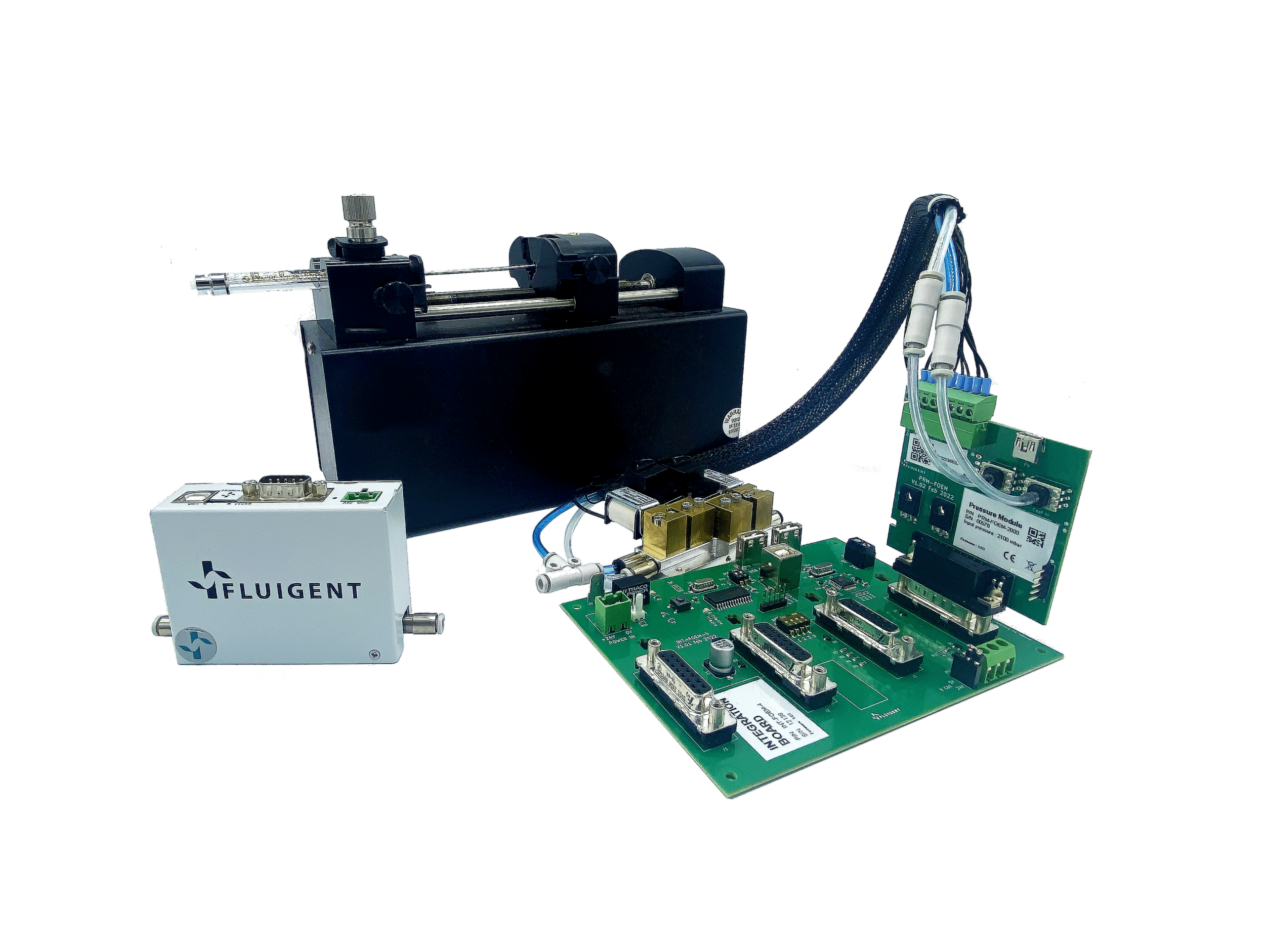
5 reasons to choose OEM pressure controllers over OEM syringe pumps for microfluidic applications
Read more- Expert Reviews: Basics of Microfluidics
Choosing the Right Microfluidic Pressure Range
Read more 
White paper: Organ on Chip
Read more- Expert Reviews: Basics of Microfluidics
Microfabrication of Microfluidic Chips: Materials and Methods
Read more - Expert Reviews: Basics of Microfluidics
Application of microfluidic chip technology
Read more
