How Does Organ-on-a-Chip Work? Advantages and Limitations
An organ-on-a-chip is a microfluidic cell culture device containing continuously perfused chambers inhabited by living human cells, arranged to reproduce tissue- and organ-level physiology [1]. How does organ on a chip work? Microchannels deliver culture medium at a defined flow rate, mechanical cues such as shear stress are applied continuously, and the resulting tissue function is measured in real time.
This review explains the mechanism step by step, then sets out the advantages and the limitations of the technology. For a broader survey, see the Fluigent white paper A guide to organs-on-chips; the Omi automated organ-on-chip platform is used as an example of an integrated system.
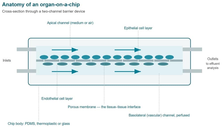
Figure 1: Cross-section of a two-channel organ-on-a-chip: epithelial and endothelial layers cultured on opposite faces of a porous membrane, each channel independently perfused.
How an Organ-on-a-Chip Works, Step by Step
An organ-on-a-chip works by combining four elements: a microfabricated chip whose channels are typically a few hundred micrometres across, human cells seeded on a porous membrane or inside a hydrogel, a pump that perfuses culture medium continuously, and an imaging or sensing route that reads out tissue function [2]. Together they reproduce a minimal, controllable unit of organ physiology.
The full experimental sequence runs as follows:
- Design and fabricate the chip. Channel geometry is chosen to deliver the target flow rate and shear stress to the cell layer, and to remain compatible with microscopy. Chip design fixes most of what the model can and cannot do later [2].
- Treat and coat the surfaces. Channels are plasma-treated or chemically functionalised, then coated with extracellular matrix proteins such as collagen, fibronectin or laminin so that cells attach and spread as they would on a basement membrane.
- Seed the cells. Primary cells, immortalised lines, induced pluripotent stem cell derivatives or dissociated organoids are introduced under static conditions and allowed to adhere. Two cell types are often seeded on opposite faces of a membrane to build a barrier [3].
- Start perfusion. Once the culture has attached, the chip is connected to a pump and medium is perfused. Flow is usually ramped rather than switched on, so that cells adapt to the new mechanical environment instead of detaching.
- Apply mechanical stimulation. Depending on the organ modelled, cyclic stretch, pulsatile flow or interstitial pressure gradients are superimposed on the baseline perfusion. In the original lung-on-a-chip, vacuum applied to side chambers stretched a 10 µm PDMS membrane to reproduce breathing movements [3].
- Measure and analyse. Barrier integrity, metabolic activity, live-cell imaging and analysis of the effluent supply the data. Because the chip is optically accessible, many readouts are non-destructive and can be repeated over days [1].
What separates this from a well plate is not miniaturisation but control. In static culture, nutrient gradients, waste accumulation and the absence of mechanical cues all drift uncontrolled.
On a chip, medium composition, flow rate, oxygen tension and shear are set by the operator, which is why these devices are formally described as microphysiological systems [4].
A single chip models one functional unit — an alveolar barrier, a liver sinusoid, a proximal tubule — not a whole organ. Linking several chips through a shared vascular circuit produces the multi-organ configurations used to study systemic responses; matured heart, liver, bone and skin niches have been connected by recirculating flow across a selectively permeable endothelial barrier [5].

Figure 2: The six stages of an organ-on-a-chip experiment, from chip fabrication through to non-destructive readout.
How Organ-on-a-Chip Devices Are Fabricated
Organ-on-a-chip fabrication starts from a microfabricated master mould or a machined substrate, from which channels a few tens to a few hundreds of micrometres deep are replicated. The chip is then bonded to a lid, ports are punched, and the assembly is sterilised. Material choice at this stage determines optical quality, gas exchange and how the device interacts with drug molecules.
Soft Lithography and PDMS Moulding
Soft lithography remains the reference method in academic research. A silicon wafer is patterned with photoresist to create a master carrying the channel layout in relief; liquid polydimethylsiloxane (PDMS) is cast against it, cured, peeled off and plasma-oxidised, after which the oxidised surfaces seal irreversibly to each other, to glass, to silicon or to oxidised polystyrene — a full design-to-sealed-device cycle in under 24 hours [6]. A porous membrane is sandwiched between two channel layers to create the tissue–tissue interface that defines a barrier model [3].
PDMS is popular for good technical reasons: it is optically clear, elastic enough to allow vacuum-actuated stretching, permeable to oxygen and carbon dioxide, and cheap to prototype with [1,3]. The same elasticity makes channel dimensions deform under pressure, which matters when flow must be quantitative.

Figure 3: Soft lithography replication: a patterned master is cast in PDMS, cured, peeled, plasma-oxidised and bonded around a porous membrane.
Which Materials Are Used to Make Organ-on-a-Chip Devices?
Beyond PDMS, three families are in routine use. Thermoplastics — cyclic olefin copolymer, polystyrene, polycarbonate — are injection-moulded or hot-embossed and retain far more compound in solution than PDMS, which is why they lead the alternatives proposed for pharmacokinetic and toxicity work. Glass offers chemical inertness and the best optical performance but is harder to structure [7]. Hydrogels such as collagen, fibrin or gelatin methacryloyl are used not as the housing but as the tissue compartment itself, letting cells remodel a three-dimensional matrix [2].
Glass sits at the other end of the trade-off. It is chemically inert, dimensionally stable under pressure, and gives the cleanest optical path, but structuring it requires etching or laser processing rather than casting, and bonding is less forgiving than plasma-sealed PDMS. Surface treatments applied to any of these materials are also not permanent: plasma-induced hydrophilicity decays over hours, so coating and seeding schedules have to be planned around it.
Commercial chips increasingly combine materials: a thermoplastic body for fluidic robustness, a glass or COC window for imaging, a membrane or gel region for the biology. Fluigent’s cell culture and organ-on-a-chip microscopy chips follow this logic, and the BE-Transflow variant adapts it to air–liquid interface culture. Fabrication route and material should be chosen against the readout planned, not the other way round.
The Role of Perfusion, Flow and Shear Stress
Perfusion is what converts a microfluidic chip into an organ model. Continuous flow renews nutrients, clears metabolic waste, establishes gradients and applies wall shear stress to the cells lining the channel. Shear is a signalling input, not a side effect: endothelial cells align with it, hepatocytes maintain metabolic function under it, and epithelial barriers tighten in response.
Wall shear stress τ in a rectangular channel much wider than it is deep is given by τ = 6 μ Q / (w h²), where μ is the dynamic viscosity of the medium, Q the volumetric flow rate, w the channel width and h its height [2]. The inverse-square dependence on height is the practical point: halving channel depth quadruples shear at constant flow rate, so small fabrication tolerances translate into large biological differences.
Physiological targets vary by tissue over several orders of magnitude. In the arterial circulation, shear above roughly 15 dyn/cm² maintains endothelial quiescence and an atheroprotective expression profile, while sustained values below about 4 dyn/cm² drive an atherogenic phenotype [8]. Hepatic tissue sits far lower: in a three-dimensional liver sinusoidal model, low shear enhanced albumin production and cytochrome P450 reductase expression in hepatocytes, whereas high shear caused loss of the hepatocyte phenotype [9]. Applying an arterial value to a liver model is a common and consequential design error.
The Fluigent shear stress calculator converts a target shear into the flow rate required for a given geometry — the calculation worth doing before any cells are seeded.
Flow profile matters as much as magnitude. Steady laminar flow suits barrier and absorption studies; pulsatile flow reproduces the cardiac cycle; recirculating flow conserves medium and lets secreted factors accumulate to physiologically meaningful concentrations, at the cost of a slowly changing composition.
Fluigent has treated these questions in depth elsewhere and this section deliberately does not repeat that material. Four expertise reviews cover the ground: controlling shear stress, microfluidic perfusion innovation, passive mechanical stimulation induced by laminar and pulsatile shear stress and the importance of recirculation in microfluidic systems. A worked protocol is available for endothelial cell culture under shear stress.

Figure 4: Laminar velocity profile in a rectangular microchannel and the geometry that determines wall shear stress. Because τ scales with 1/h², channel height dominates the result.
Monitoring Flow and Blood-Flow-Like Conditions
Monitoring closes the loop between the pump and the biology. Setting a flow rate is not the same as delivering it: channel resistance changes as cells proliferate and matrix is deposited, bubbles alter hydraulic resistance abruptly, and evaporation shifts reservoir levels over a multi-day experiment.
Inline flow sensors report what the tissue actually receives and feed that value back to the controller.
In a pressure-driven setup, a flow unit sensor placed upstream of the chip measures the real flow rate and allows the controller to adjust applied pressure automatically. The same arrangement is used in integrated research platforms, where a flow sensor tracks both the delivered flow rate and potential channel blockage during long automated runs [10]. Without measurement, a drift in resistance is silently converted into a drift in the mechanical stimulus applied to the cells, and there is no record of it in the data.
Reproducing blood-flow-like conditions adds further requirements. Pulsatility must be delivered with a defined frequency and waveform rather than as incidental pump ripple. Where whole blood or blood substitutes are perfused, viscosity is higher and shear-dependent, so the flow rate calculated for culture medium no longer produces the intended shear.
Recent Innovations in Blood-Flow Monitoring
Recent development in this area has moved from single-point measurement toward integrated, continuous sensing. Fully modular platforms now combine physical, biochemical and optical sensing with a multi-organ chip system through a fluidics-routing breadboard, achieving automated in situ measurement of microenvironment parameters over extended periods [10]. Electrodes for transepithelial electrical resistance, integrated oxygen sensing and imaging-based readouts are increasingly combined with flow data, so that a mechanical input and a biological response can be correlated on the same time axis.
The remaining challenges are honest ones: sensor footprint competes with chip real estate, calibration drifts over long culture periods, and multiplexed platforms generate volumes of data that few laboratories are equipped to analyse systematically.
At the field level, the absence of agreed design, qualification and reporting conventions remains one of the principal barriers to comparing results between laboratories and to deployment beyond specialist groups [11].
Advantages of Organ-on-a-Chip Technology
The advantages of organ-on-a-chip technology come from combining human cells with physiological mechanical conditions in an optically accessible, low-volume format. This yields models that are more predictive than static culture for many endpoints, and directly observable in a way that neither static culture nor animal studies allow [1].
Human-Relevant Physiology
The models are built from human cells, which removes the species-extrapolation step that limits animal studies. Induced pluripotent stem cell technology extends this to donor-specific models, the route by which organ-on-a-chip systems are expected to contribute to disease modelling, drug development and personalized medicine [12,13].
Physiological relevance is also structural. Co-culturing epithelium with endothelium across a membrane reproduces barrier function, and adding immune cells to the perfusion stream reproduces recruitment; the original lung chip reproduced organ-level inflammatory responses to bacteria and cytokines introduced into the alveolar compartment [3]. Disease models built this way — inflamed gut, fibrotic liver, tumour microenvironments in cancer research — reproduce mechanisms a monolayer cannot.
Dynamic, Perfused Culture
Continuous perfusion maintains a stable nutrient and oxygen supply and removes waste, which extends viable culture from days to weeks. Cells retain differentiated phenotypes markedly longer under flow, and the effect is dose-dependent rather than monotonic: in a liver sinusoidal model, low shear improved synthetic and metabolic function while high shear degraded it [9].
Flow also organises tissue. Recirculating vascular flow between compartments allows tissue niches with different optimal media to be maintained in one system while still communicating, which is the basis of current multi-organ chips [5].
Real-Time Imaging and Readouts
Chips are designed to sit on a microscope stage, so the same tissue can be imaged repeatedly over the course of an experiment. High-resolution, real-time optical imaging of living cells in a functional tissue context is one of the defining capabilities of the format [1].
The small effluent volume is an asset for analysis. Secreted proteins and metabolites accumulate to detectable concentrations in microlitres of medium, and integrated electrochemical and optical sensors can report barrier resistance, oxygen and biomarker levels without opening the system [10].
Reduced Reagent and Cell Consumption
A chip operates with medium volumes and cell numbers orders of magnitude below conventional formats, which changes what is feasible when working with scarce primary cells, patient-derived material or expensive drug candidates [2].
The effect is most visible where material is genuinely scarce. Patient-derived primary cells, biopsy-derived organoids and iPSC lines are produced in numbers that do not stretch to plate-format screening, and a chip format lets the same donor material support several conditions instead of one. Expensive compound stocks benefit for the same reason.
Lower consumption also lowers the barrier to iteration, and the regulatory context now recognises the approach: the FDA Modernization Act 2.0, signed on 29 December 2022, authorises sponsors to use alternatives to animal testing — including cell-based assays and computer models — when seeking an exemption to investigate the safety and effectiveness of a drug [14].
Limitations and Challenges of Organ-on-a-Chip Systems
The limitations of organ-on-a-chip systems are as real as the advantages. Throughput, material artefacts, operational fragility and cost currently keep these devices in specialist hands rather than in routine screening pipelines [11].

Figure 5: Advantages and limitations of organ-on-a-chip technology side by side. Both follow from the same property: deliberate control of the cellular microenvironment.
Throughput and Standardisation
Most chips are operated in units of one to a few dozen, against 96 or 384 wells in a plate. Multiplexed platforms exist, but scaling perfusion, imaging and sampling across many chips in parallel remains an engineering problem rather than a solved one.
The response from the field has been to converge on plate footprints and standard automation interfaces, so that chips can be handled by liquid handlers and plate readers already installed in screening laboratories. This raises throughput without solving it: perfusion, imaging and sampling still have to scale together, and a platform that multiplexes culture but not readout simply moves the bottleneck.
Standardisation lags further behind. Chip geometries, flow protocols, coating procedures and readouts differ between laboratories, which makes results difficult to compare; design and process conventions, not scientific capability, are identified as the main brake on wider deployment [11]. Qualification frameworks for defined contexts of use in drug development are still under construction [4].
Material Absorption and PDMS Effects
PDMS absorbs small hydrophobic molecules into its bulk, depleting them from the medium and changing solution concentrations enough to alter experimental outcomes [15]. For a lipophilic drug candidate this distorts dose–response curves and toxicity estimates in exactly the studies the technology is meant to improve: measured drug responses shift when the same bioassay is run in a PDMS device [16].
Mitigations exist — surface coatings, thermoplastic or glass chips, correcting measured rather than nominal concentrations [7] — but each has a cost in fabrication complexity or flexibility. The deformability of PDMS under pressure is a secondary but non-trivial concern for quantitative work.
Bubble Management and Reproducibility
Air bubbles are the most common practical failure mode and a recognised obstacle to running long-term microfluidic cell culture [17]. A bubble entering a channel blocks flow, shears cells off the surface and can end a two-week experiment in seconds. Degassing medium, using bubble traps and priming carefully are routine countermeasures, not optional refinements.
In practice the countermeasures are procedural as much as hardware. Medium is degassed or pre-equilibrated in the incubator before use, tubing and chips are primed slowly with the outlet open, and connections are made under liquid so that no air is trapped at a fitting. A bubble trap upstream of the chip catches what these steps miss [17].
Reproducibility suffers from the manual steps that remain: seeding density, coating uniformity and connection procedure all vary between operators, so chip-to-chip variability frequently exceeds well-to-well variability in plates and raises the replicate count needed for statistical power.
Cost and Technical Expertise
Running these systems requires competence in cell biology, fluid mechanics and microscopy at once, and few teams start with all three. The learning curve is measured in months, and early failures are usually fluidic rather than biological.
The capital cost of pumps, controllers, sensors and an imaging setup is significant, and consumable chips add a recurring cost per experiment. Integrated platforms reduce the technical burden by handling flow control and monitoring automatically — the trade-off is between building a bespoke setup and buying a validated one [11].
Equipment Needed to Run an Organ-on-a-Chip Experiment
A working organ-on-a-chip setup needs four things: a chip, a means of driving flow, a way of measuring that flow, and the fluidic connections in between. An incubator and a microscope complete the installation. The choices made here determine how stable and reproducible the mechanical environment will be [2].
Choosing a Pump: Pressure-Based vs Peristaltic
Peristaltic pumps are inexpensive and recirculate easily, but they generate pulsation from the rollers themselves, superimposed on any physiological waveform the experiment intends to apply, and tubing fatigue changes delivered flow over long runs.
Syringe pumps deliver smooth flow but have finite volume and respond slowly to changes in resistance.
Pressure-based control applies a regulated pressure to the medium reservoir; combined with an inline flow sensor, it delivers pulseless, fast-responding and stable flow, and can reproduce a defined pulsatile waveform on demand. The Flow EZ and the wider LineUP Series implement this approach. For a direct comparison see the application note on peristaltic pumps versus pressure-based flow control for organ-on-chip and the paper highlight on pressure-driven flow controllers versus syringe pumps.
Flow Sensors and Monitoring
A flow sensor is not an accessory. In pressure-driven operation it provides the measured value that closes the control loop, converting a pressure setpoint into a guaranteed flow rate, and it gives a continuous record of what the culture experienced [10].
Sensor range should be matched to the intended flow rate rather than to the pump, and placed upstream of the chip to limit dead volume. Recording flow alongside imaging timestamps makes it possible to attribute an anomaly to a fluidic event rather than to biology.
Chips and Connectors
The chip defines the geometry, the material and therefore the shear stress achievable and the compound absorption expected [15,16]. Connector choice — tubing internal diameter, fitting type, dead volume — determines system compliance, and a compliant system responds sluggishly to flow changes and traps bubbles.
Integrated platforms bundle these elements. The Omi platform combines pressure-based flow control, sensing and recirculation in an incubator-compatible unit, which removes much of the assembly work from the user. Whichever route is taken, the components should be specified together rather than acquired piecemeal.


Figure 6: Equipement for organ-on-a-chip culture
Conclusion
Organ-on-a-chip technology works by holding human cells in a microfabricated, continuously perfused environment where flow, shear stress and biochemical composition are set deliberately and measured continuously.
The advantages — human relevance, dynamic culture, real-time readouts and low consumption — follow directly from that control. So do the limitations: modest throughput, material artefacts, sensitivity to bubbles, and a real requirement for technical skill.
The practical conclusion for a new user is that the biology is only as good as the fluidics beneath it. Deciding the target shear stress first, then choosing chip geometry, pump and sensor to deliver it reliably, avoids the majority of the failures that end organ-on-a-chip experiments early.
Last updated: September 2026. This review is periodically updated to reflect new developments in microphysiological systems.
Frequently Asked Questions
What Are the Main Advantages and Disadvantages of Organ-on-a-Chip?
The main advantages are human-relevant physiology, perfused dynamic culture, real-time optical readouts and low reagent and cell consumption. The main disadvantages are low throughput compared with well plates, absorption of hydrophobic compounds by PDMS, vulnerability to air bubbles, absence of standardisation between laboratories, and the combined cost and expertise required to run the systems reliably [15,11].
What Are the Biggest Challenges in Organ-on-a-Chip?
The biggest challenges are scaling to screening throughput, standardising chip designs and protocols so that results are comparable across laboratories, eliminating material-related artefacts in pharmacokinetic and toxicity studies, and achieving regulatory qualification for defined contexts of use [4,11]. Operationally, bubble management and chip-to-chip variability remain the most frequent causes of failed experiments [17].
Which Pump Is Best for Organ-on-a-Chip: Peristaltic or Pressure-Based?
Pressure-based control is generally preferable when shear stress must be stable and quantitative, because it delivers pulseless flow, responds quickly to changing channel resistance and — with an inline sensor — regulates the actual flow rate rather than a nominal one. Peristaltic pumps remain a lower-cost option for simple recirculation where pulsation and long-term drift are acceptable.
How Is Shear Stress Calculated in a Microfluidic Chip?
For a rectangular channel much wider than it is deep, wall shear stress is τ = 6 μ Q / (w h²), with μ the medium viscosity, Q the flow rate, w the width and h the height [2]. Because shear scales with the inverse square of channel height, geometry dominates the result. The Fluigent shear stress calculator performs the conversion for a given chip and target value.
Related Expertises
-
Expert Reviews: Basics of Microfluidics Organ-on-a-Chip Companies: Market Overview and How to Choose a Supplier Read more
-
Expert Reviews: Basics of Microfluidics What Is Organ-on-a-Chip? A Complete Guide Read more
-
Expert Reviews: Basics of Microfluidics The Importance of Recirculation in Microfluidic Systems: Principles and Applications Read more
-
Expert Reviews: Basics of Microfluidics Optimizing Microfluidic Perfusion: Best Practices and Innovations Read more
-
Microfluidic Application Notes Controlling Flow Rate and Shear Stress with Omi™ to Study Endothelial Cell Response Read more
-
Microfluidics Article Reviews Pressure-driven flow controllers vs. Syringe pumps: A flow precision evaluation for optical blood imaging. Read more
-
Expert Reviews: Basics of Microfluidics Why Control Shear Stress in Cell Biology? Read more
-
Microfluidic Application Notes Peristaltic Pump vs Pressure-Based Microfluidic Flow Control for Organ on Chip applications Read more
-
Expert Reviews: Basics of Microfluidics Passive and active mechanical stimulation in microfluidic systems Read more
References
- Bhatia SN, Ingber DE. Microfluidic organs-on-chips. Nature Biotechnology 2014;32(8):760–772. doi.org/10.1038/nbt.2989
- Leung CM, de Haan P, Ronaldson-Bouchard K, Kim G-A, Ko J, Rho HS, Chen Z, Habibovic P, Jeon NL, Takayama S, Shuler ML, Vunjak-Novakovic G, Frey O, Verpoorte E, Toh Y-C. A guide to the organ-on-a-chip. Nature Reviews Methods Primers 2022;2:33. doi.org/10.1038/s43586-022-00118-6
- Huh D, Matthews BD, Mammoto A, Montoya-Zavala M, Hsin HY, Ingber DE. Reconstituting organ-level lung functions on a chip. Science 2010;328(5986):1662–1668. doi.org/10.1126/science.1188302
- Low LA, Mummery C, Berridge BR, Austin CP, Tagle DA. Organs-on-chips: into the next decade. Nature Reviews Drug Discovery 2021;20(5):345–361. doi.org/10.1038/s41573-020-0079-3
- Ronaldson-Bouchard K, Teles D, Yeager K, Tavakol DN, Zhao Y, Chramiec A, Tagore S, Summers M, Stylianos S, Tamargo M, et al. A multi-organ chip with matured tissue niches linked by vascular flow. Nature Biomedical Engineering 2022;6(4):351–371. doi.org/10.1038/s41551-022-00882-6
- Duffy DC, McDonald JC, Schueller OJA, Whitesides GM. Rapid prototyping of microfluidic systems in poly(dimethylsiloxane). Analytical Chemistry 1998;70(23):4974–4984. doi.org/10.1021/ac980656z
- Campbell SB, et al. Beyond polydimethylsiloxane: alternative materials for fabrication of organ-on-a-chip devices and microphysiological systems. ACS Biomaterials Science & Engineering 2021;7(7):2880–2899. doi.org/10.1021/acsbiomaterials.0c00640
- Malek AM, Alper SL, Izumo S. Hemodynamic shear stress and its role in atherosclerosis. JAMA 1999;282(21):2035–2042. doi.org/10.1001/jama.282.21.2035
- Li W, Li P, Li N, Du Y, Lü S, Elad D, Long M. Matrix stiffness and shear stresses modulate hepatocyte functions in a fibrotic liver sinusoidal model. American Journal of Physiology – Gastrointestinal and Liver Physiology 2021;320(3):G272–G282. doi.org/10.1152/ajpgi.00379.2019
- Zhang YS, Aleman J, Shin SR, Kilic T, Kim D, Mousavi Shaegh SA, Massa S, Riahi R, Chae S, Hu N, et al. Multisensor-integrated organs-on-chips platform for automated and continual in situ monitoring of organoid behaviors. PNAS 2017;114(12):E2293–E2302. doi.org/10.1073/pnas.1612906114
- Alver CG, Drabbe E, Ishahak M, Agarwal A. Roadblocks confronting widespread dissemination and deployment of Organs on Chips. Nature Communications 2024;15:5118. doi.org/10.1038/s41467-024-48864-3
- Ronaldson-Bouchard K, Vunjak-Novakovic G. Organs-on-a-chip: a fast track for engineered human tissues in drug development. Cell Stem Cell 2018;22(3):310–324. doi.org/10.1016/j.stem.2018.02.011
- Ingber DE. Human organs-on-chips for disease modelling, drug development and personalized medicine. Nature Reviews Genetics 2022;23(8):467–491. doi.org/10.1038/s41576-022-00466-9
- FDA Modernization Act 2.0, S.5002, 117th Congress (2021–2022). Enacted 29 December 2022 as §3209 of the Consolidated Appropriations Act, 2023. (Legislative source, not a peer-reviewed paper.) congress.gov/bill/117th-congress/senate-bill/5002
- Toepke MW, Beebe DJ. PDMS absorption of small molecules and consequences in microfluidic applications. Lab on a Chip 2006;6(12):1484–1486. doi.org/10.1039/b612140c
- van Meer BJ, et al. Small molecule absorption by PDMS in the context of drug response bioassays. Biochemical and Biophysical Research Communications 2017;482(2):323–328. doi.org/10.1016/j.bbrc.2016.11.062
- Sung JH, Shuler ML. Prevention of air bubble formation in a microfluidic perfusion cell culture system using a microscale bubble trap. Biomedical Microdevices 2009;11(4):731–738. doi.org/10.1007/s10544-009-9286-8