Microfluidic Bubble Trap or Degasser? How to Remove Air Bubbles
Air bubbles, a common issue in microfluidic experiments, can significantly affect performance and reliability of the setups, impacting experimental outcomes and data accuracy. Addressing this issue is crucial for advancing the field.
Microfluidic Bubble Trap or Degasser? How to Remove Air Bubbles
A microfluidic bubble trap vents bubbles already travelling in an aqueous flow through a hydrophobic membrane before they reach the chip, while an inline degasser removes dissolved gas so that fewer bubbles form [1,2]. Use the trap to protect the chip, the degasser to stop bubbles forming, and both for long runs.
This page covers bubbles in microfluidic chips, tubing and reservoirs, not in syringes for injection, screens or aquaria.
Microfluidics have revolutionized various fields including biology, chemistry, and medicine [3]. However, one of the common challenges faced in microscale fluidic experiments is the presence of air bubbles. Their presence can significantly affect the performance and reliability of microfluidic devices, leading to inaccurate results or even device failure.
Key takeaways
- A microfluidic bubble trap vents bubbles already travelling in an aqueous flow through a hydrophobic PTFE membrane, before they reach the chip [1].
- An inline degasser removes dissolved gas through a non-porous semi-permeable membrane under vacuum, so fewer bubbles form downstream [2].
- Bubbles nucleate on surface irregularities when a pressure drop or a temperature rise leaves the solution supersaturated [4].
- Bubbles destabilise flow, slow system response, clog channels and valves, damage cell membranes and distort measurements.
- Long perfusion runs often justify both devices: the degasser upstream to limit new bubbles, the trap at the inlet as the last barrier.
Where do air bubbles come from?
Bubbles can vary in size from a microscopical to a visible scale. In the context of microfluidic systems, they are typically small due to the microscale dimensions of the devices, but their impact can be significant. Gas bubbles can originate from various sources. Understanding their formation process is the first step towards developing strategies to prevent them from forming and improve the performance and reliability of the experiments
Dissolved Gases
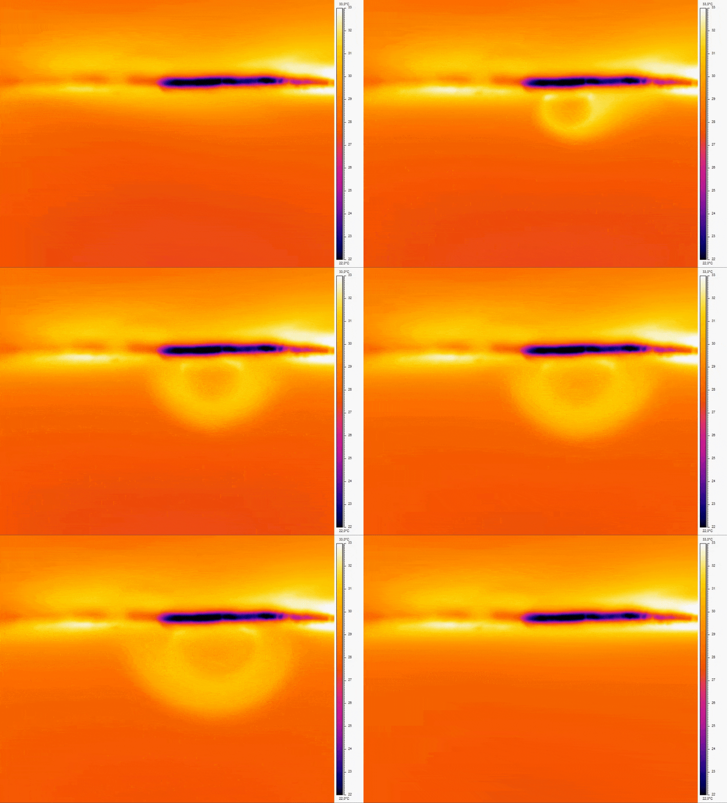
One common origin of air bubble formation is the presence of dissolved gases in the liquid. Microfluidic experiments usually involve the movement of liquids that can create pressure differentials. High-pressure conditions within microchannels can contain significant amounts of dissolved gases. When pressure decreases, gas solubility diminishes, making the formation of bubbles more likely. Temperature changes can also influence gas solubility (Figure 1). For instance, when a liquid reagent is introduced directly from a refrigerated environment, it enters the system at a lower temperature than the fluids in the system, increasing the potential for bubble apparition.
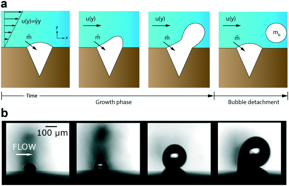
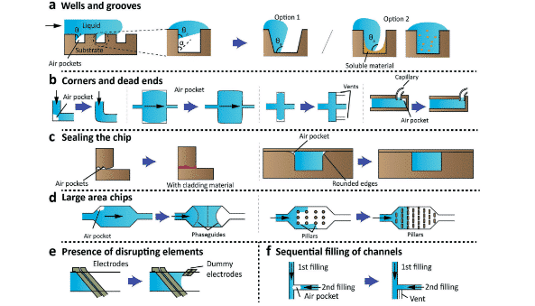
Bubbles do not spontaneously emerge due to environmental changes alone. Minuscule irregularities found on the surfaces within the microfluidic system act as sites where tiny volumes of air can become trapped (Figure 2a). Under stable conditions, the trapped gas remains static. Yet, any perturbation in the surrounding liquid’s pressure can either dissolve the gas or induce a gas flux within the irregularity, causing the air pocket to grow (Figure 2b). It’s important to note that the nucleation point remains in the same location, giving rise to the possibility of new gas bubbles forming in the future [4].
Physical characteristics of microfluidic setup
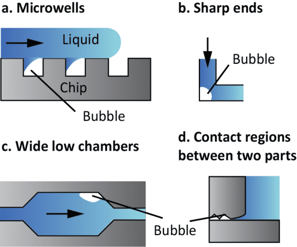
The configuration of microfluidic platform also plays a role. Hydrophobic surfaces and surface roughness on channel walls can trap air pockets, creating sites for bubble formation. Some components within microfluidic devices, such as valves and pumps, may act as bubble generators during their operation. Abrupt changes in channel geometry such as sharp angles, corners, sudden expansions or contractions, can also induce pressure fluctuations, leading to generation of bubbles (Figure 3).
Porous material
The introduction of air into your system doesn’t only occur during the filling step of channels or when there are leaks that allow air to enter. In fact, microfluidic components are often made from materials like polydimethylsiloxane (PDMS), which are permeable to gases. Ambient air can pass through the device walls, leading to the gradual formation and accumulation of small bubbles within the liquid channels.
Chemical Reactions and Fluid properties
Some chemical reactions used in microfluidic experiments can produce gases as a byproduct, resulting in the release of gases in the solution. Even the presence of surface-active agents, like surfactants, can either promote or inhibit formation of bubbles, depending on their concentration and properties.
What air bubbles break in a microfluidic experiment
Bubbles compromise an experiment in five ways: unstable flow, slower system response, clogged channels and valves, damaged cell membranes, and interference with mixing and measurements.
Flow Instability
The presence of bubbles can disrupt the uniformity and consistency of fluid movement through microchannels, causing an important flow instability. This can lead to unwanted fluctuations in flow rate and pressure (Figure 4). Flow instability can compromise the reliability and reproducibility of experiments, affecting the accuracy and success of microfluidic processes.

System Response Time
Bubbles can significantly affect the response time of microfluidic systems. When they enter the microchannels, they can create delays in system response. This is especially relevant in applications that require rapid changes in fluid composition, concentration, or flow rates. As a result, the overall efficiency and real-time control of microfluidic processes may be compromised.
Clogging of Microfluidic Networks
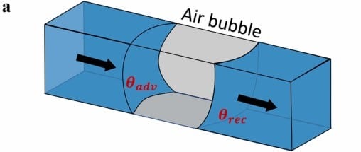
The accumulation of bubbles in the setup can lead to physical blockages (Figure 5). They become trapped in narrow channels, junctions, or valve openings, preventing the fluid from flowing through the device. This clogging prevents the system from functioning as designed, increases the time needed to reach pressure equilibration, and leads to the failure of many biological and chemical experiments. Clogging does not only prevent the progression of experiments but also necessitates time-consuming maintenance to clear obstructions.
Damage to Cell Membranes
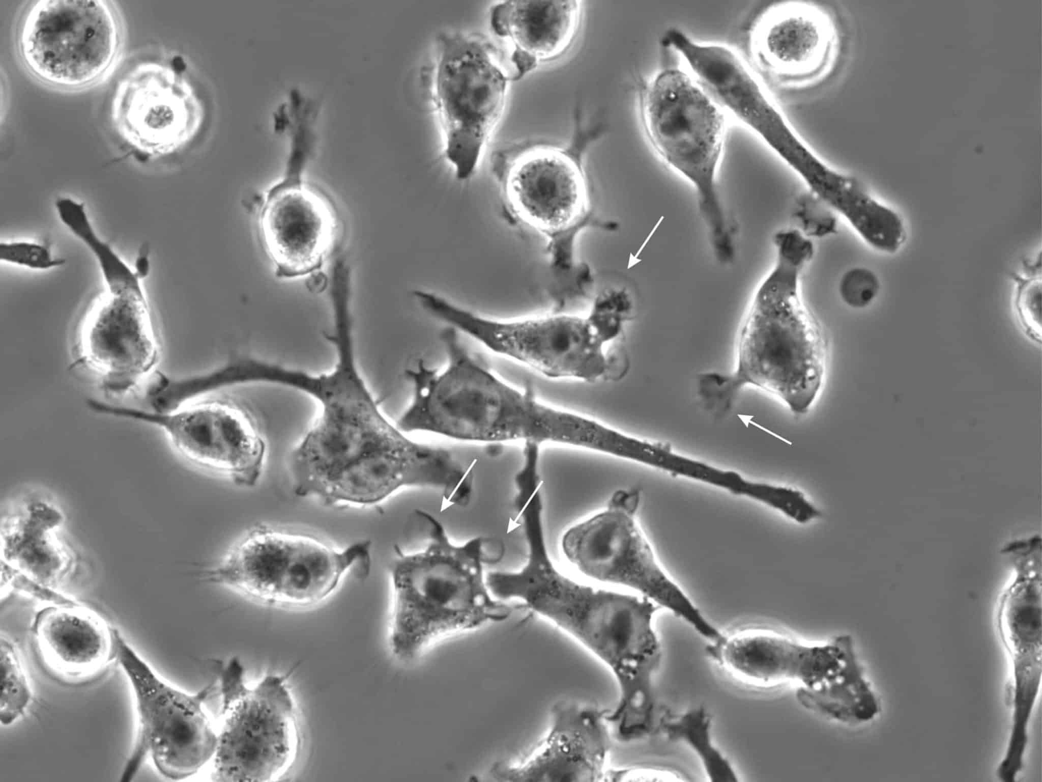
In biological applications, air bubbles can damage cell membranes, affecting the viability and function of the cells. They present interfacial tension that can apply shear stress on cells and even lead to cellular death (Figure 6). Additionally, the interfaces between the gas bubbles and the liquid are an area where particles and proteins can aggregate, leading to artifacts in the experiment. These artifacts can interfere with the measurement and analysis of the biological samples, reducing the accuracy and reliability of the results.
Analytical Interferences
Air bubbles can alter chemical mixing by acting as physical barriers. These barriers prevent the chemicals from properly touching each other. As a result, the speed of reactions and the outcome are affected.
These tiny air pockets can also distort detection outcomes, causing inaccurate readings. They can obstruct current conduction and alter optical paths, impacting measurements and observations.
This can cause incorrect measurements of light absorption or fluorescence, leading to inaccurate data collection and interpretation. Furthermore, bubbles passing through microfluidic channels can damage the functionalization of the microfluidic wall, such as removing previously made chemical grafting.
How to prevent air bubbles: five steps
To prevent air bubbles in a microfluidic setup, degas at the source and remove the places where bubbles can collect. Five steps cover most situations:
- Degas liquids before use.
- Choose low-permeability materials.
- Prime and fill without dead ends.
- Control pressure ramps.
- Keep connections wetted.
Step 1: Degas liquids before use
Degas buffers, media and reagents before they enter the setup, and let refrigerated solutions reach working temperature first.
Solubility falls when pressure drops or temperature rises, so a solution saturated at the bench can become supersaturated on a heated stage or downstream of a restriction. Supersaturation is one of the two main conditions behind bubble nucleation, with surface nuclei [4].
Step 2: Choose low-permeability materials
Use tubing, chips and reservoirs that let little air diffuse through their walls, with hydrophilic channel surfaces.
To limit gas diffusion, choose materials with low gas permeability designed for microfluidic applications. To decrease the probability of bubble entrapment, opt for hydrophilic surfaces and apply treatments that enhance this property.
Surface properties decide whether the flow wets channel corners or bridges over them and leaves air behind [4]. Our guide to tubing selection compares material permeability.
Step 3: Prime and fill without dead ends
Fill the circuit through smooth geometries, avoiding dead-end branches and dead volumes where air stays behind.
Optimize the design of microfluidic setups to minimize geometries that increase the probability of generating bubbles. Smooth transitions between different channel widths and shapes can reduce pressure fluctuations that trigger their formation (Figure 7). Additionally, ensuring correct installation and configuration of all system components can prevent air from entering the system.
Components with dead volumes are a common entry point for bubbles [1]; the dead volume definitions show where they sit in a circuit.
Step 4: Control pressure ramps
Change pressure progressively rather than abruptly, so that sudden drops do not bring bubbles out of solution.
Implementing a flow controller, such as the Flow EZ™, into your setup ensures that pressure variations are minimal, reducing the risk of air bubble formation. By monitoring and adjusting pressure flow rate in microfluidic applications such as droplet generation, users improve the overall reliability of the experiment compared to other methods like syringes and peristaltic pumps.

Step 5: Keep connections wetted
Make every connection liquid-to-liquid and keep fittings tight, so that no air is drawn in when lines are joined.
Air enters each time a line is connected, a reservoir is changed or a fitting loosens. A dry fitting can trap air in its crevices, and these surface nuclei can keep releasing bubbles later in the run [4].
Removing bubbles that are already in the system
Bubbles already in the system are removed actively, by an inline degasser working under vacuum, or passively, by a microfluidic bubble trap that vents them before the chip [1,2].
| Criterion | Inline degasser (active) | Microfluidic bubble trap (passive) |
|---|---|---|
| Principle | Gas diffuses through a non-porous semi-permeable membrane into a vacuum chamber [2] | Bubbles are vented through a hydrophobic microporous PTFE membrane; the flow continues [1] |
| Position | Inline, upstream of critical components such as the chip [2] | Between the point where bubbles appear and the chip [1] |
| Acts on | Dissolved gas, and bubbles already formed [2] | Bubbles already travelling with the flow [1] |
| Compatible media | Aqueous solutions and a wide range of organic solvents [2] | Aqueous flows only; organic liquids may leak [1] |
| Requires | A vacuum source [2] | Flow pushed towards the trap; not used in withdrawal mode [1] |
| Best suited to | Bubbles forming from solution inside the setup | Bubbles introduced at connections, reservoir changes or priming |
Active degassing with an inline degasser
Active degassing acts before bubbles form. The degasser sits inline, upstream of the chip, connected to a vacuum or negative pressure source such as a compact vacuum pump [2].
There are different methods for degassing liquids, such as vacuum degassing, helium sparging or sonication [6]. However, these methods have some limitations, such as high cost, high maintenance, high noise, high waste, and/or low efficiency. An inline alternative is the Fluid Degassing Device. It is designed to prevent unwanted bubbles from forming and can also remove already formed bubbles. It uses a non-porous semi-permeable membrane that allows gas molecules to diffuse out of the liquid and into a vacuum chamber [2] (Figure 8).
Choose a degasser when bubbles form from solution inside the setup: long experiments, heated stages, restrictions in narrow channels, or organic phases a membrane trap cannot handle [2].


Figure 8. Principle of the Fluid Degassing Device: the liquid flows through a short length of semi-permeable tubing inside a small chamber held under partial vacuum; dissolved gas migrates across the tubing wall into the chamber and is pumped away [2].
How a microfluidic bubble trap works
A microfluidic bubble trap has two fluid ports and a gas exhaust. Bubbles entering with the flow cross a hydrophobic microporous PTFE membrane and leave through the exhaust, while the aqueous solution, repelled by the membrane, continues to the outlet [1] (Figure 9).

Figure 9. Fluigent setup using a bubble trap: a Flow EZ™ pressure controller pressurises a tube reservoir, and the Bubble Trap is connected on the outlet line so that bubbles are vented before the liquid reaches the chip [1].
Incorporate a Bubble Trap to eliminate bubbles already traveling with the microfluidic system and keep them from sensitive regions of the setup, such as microfluidic chips. Connect its inlet where bubbles are likely to be present and its outlet to the downstream device [1].
Always push the flow towards the trap, as withdrawal mode may generate bubbles, and flush it with deionised or distilled water after use to prevent salt crystals [1].
Choose a trap when bubbles enter mechanically, at connections, reservoir changes or priming, and the solution is aqueous.
When to use both a degasser and a microfluidic bubble trap
Some setups need both devices. Long perfusion runs and gas-producing chemistry produce bubbles continuously, so a single barrier may not be enough. The degasser limits what comes out of solution; the trap at the inlet catches what still forms or enters at connections, a combination suited to perfusion practice for long-term culture (Figure 10).
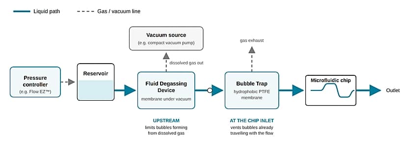
Figure 10. Example circuit combining an inline degasser upstream, connected to a vacuum source, and a microfluidic bubble trap at the chip inlet, which vents bubbles still travelling with the flow [1,2].
Frequently Asked Questions
How do you remove an air bubble from a microfluidic chip?
If bubbles keep arriving from the circuit, place a bubble trap at the chip inlet to vent them before the channels [1]. If a bubble is lodged in the chip, re-prime with degassed solution, which can dissolve a small trapped bubble [4]; an inline degasser keeps the supply degassed [2].
Do air bubbles damage cells in microfluidic culture?
Yes. Bubbles flowing over adherent cells expose them to a moving air–liquid interface, and the interfacial tension at that meniscus can damage cell membranes and kill cells [7]. Bubbles entering culture channels can also cause device delamination [7].
Conclusion
On this page, we focused on the importance of addressing air bubbles in microfluidic systems. They can originate from various sources, potentially disrupting experiments and compromising data accuracy. To resolve this issue, we recommend optimizing system design, material selection, and flow control. Additionally, using degassing methods and incorporating Bubble traps in the microfluidic setup can effectively prevent and remove bubbles. In essence, a combination of these strategies is essential to ensure reliable and accurate experiments.
Related products


Related Resources
-
Expert Reviews: Basics of Microfluidics 10 Tips for Reliable Droplet Generation Read more
-
Microfluidic Application Notes Microbubble formation using the RayDrop Read more
-
Expert Reviews: Basics of Microfluidics How to choose a microfluidic chip Read more
-
Microfluidics White Papers Droplet-based Microfluidics – A Complete Guide Read more
-
Expert Reviews: Basics of Microfluidics Flow control for droplet generation using syringe pumps and pressure-based flow controllers Read more
-
Expert Reviews: Basics of Microfluidics Flow Control Technologies: Comparison between peristaltic, syringe and pressure pumps for microfluidic applications Read more
-
Expert Reviews: Basics of Microfluidics Microfluidic volume definitions Read more
References
- Fluigent. (n.d.). Bubble Trap. Retrieved October 15, 2026, from https://www.fluigent.com/research/instruments/accessories/bubble-trap/
- Fluigent. (n.d.). Fluid degassing device for microfluidic system. Retrieved October 15, 2026, from https://www.fluigent.com/research/instruments/accessories/fluid-degassing-device/
- Figeys, D., & Pinto, D. (2000). Lab-on-a-chip: A revolution in biological and medical sciences. Analytical Chemistry, 72(9), 330A–335A. https://doi.org/10.1021/ac002800y
- Pereiro, I., Fomitcheva Khartchenko, A., Petrini, L., & Kaigala, G. V. (2019). Nip the bubble in the bud: A guide to avoid gas nucleation in microfluidics. Lab on a Chip, 19(14), 2296–2314. https://doi.org/10.1039/C9LC00211A
- Zhao, X., Ma, C., Park, D. S., Soper, S. A., & Murphy, M. C. (2022). Air bubble removal: Wettability contrast enabled microfluidic interconnects. Sensors and Actuators B: Chemical, 361, 131687. https://doi.org/10.1016/j.snb.2022.131687
- Brown, J. N., Hewins, M., Van Der Linden, J. H. M., & Lynch, R. J. (1981). Solvent degassing and other factors affecting liquid chromatographic detector stability. Journal of Chromatography A, 204, 115–122. https://doi.org/10.1016/S0021-9673(00)81646-5
- Williams, M. J., Lee, N. K., Mylott, J. A., Mazzola, N., Ahmed, A., & Abhyankar, V. V. (2019). A low-cost, rapidly integrated debubbler (RID) module for microfluidic cell culture applications. Micromachines, 10(6), 360. https://doi.org/10.3390/mi10060360
