Gut-on-Chip Modeling: From Chip Development to Perfusion
Adoption of organ-on-a-chip (OOAC) technologies can require microfabrication facilities to develop specialized models. This can limit adoption in research labs. Recognizing this barrier, at the Institut Pasteur de Lille, the team of E. Delannoy, A Grassart, et. al. has developed the 3DP-μGut, an accessible gut-on-chip model fabricated via desktop stereolithography (SLA) 3D printing.
In the publication Lab on a Chip (2025), Flow EZ flow controllers and the Omi OOAC Platform were used for continuous perfusion. By precisely controlling the flow rate, the platform achieved physiologically relevant epithelial maturation, sustained viability, and the ability to model complex host–microbe interactions under dynamic conditions. This represents a step toward broadening the use of organ-on-chip technology for biomedical research.
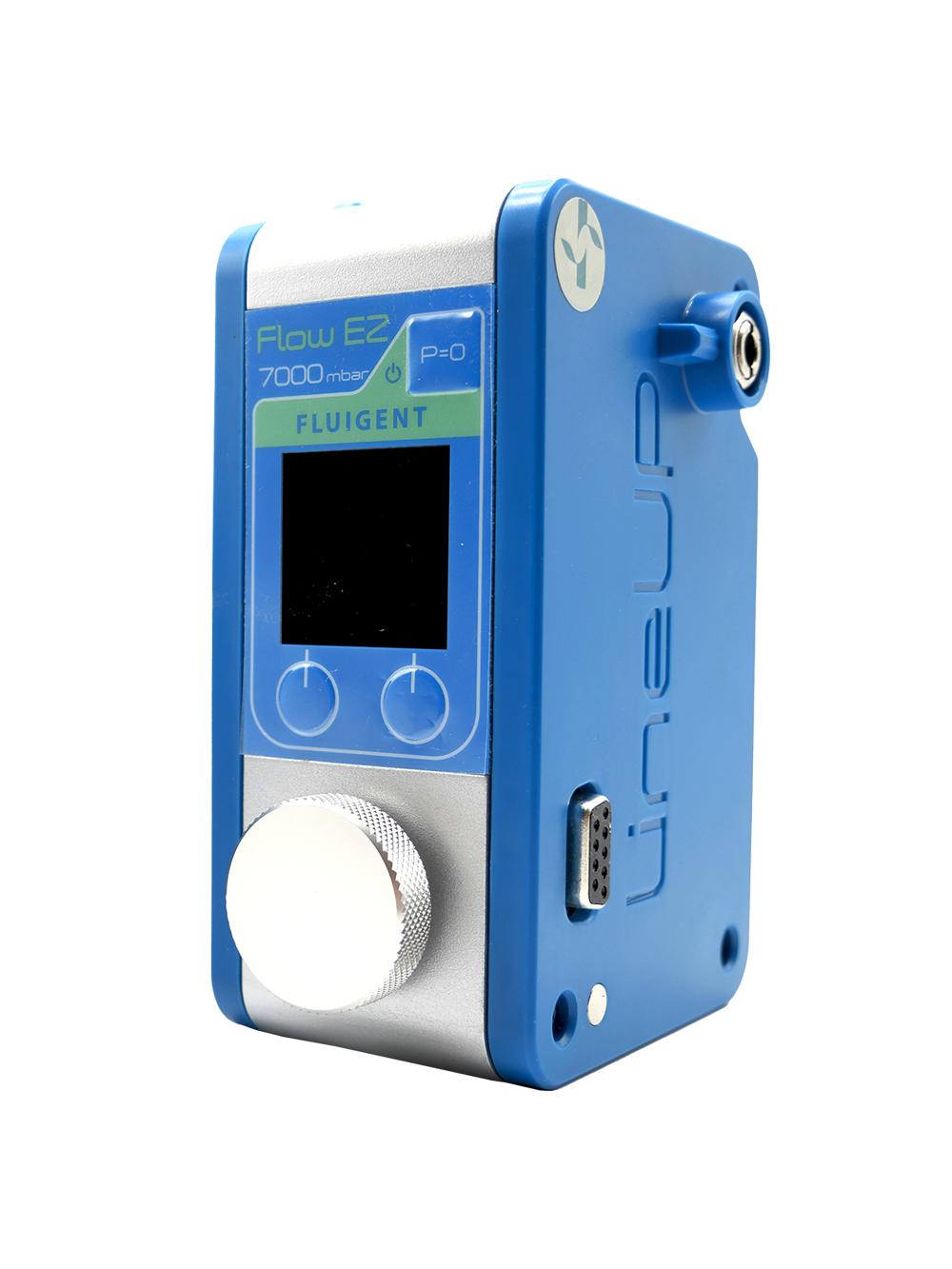
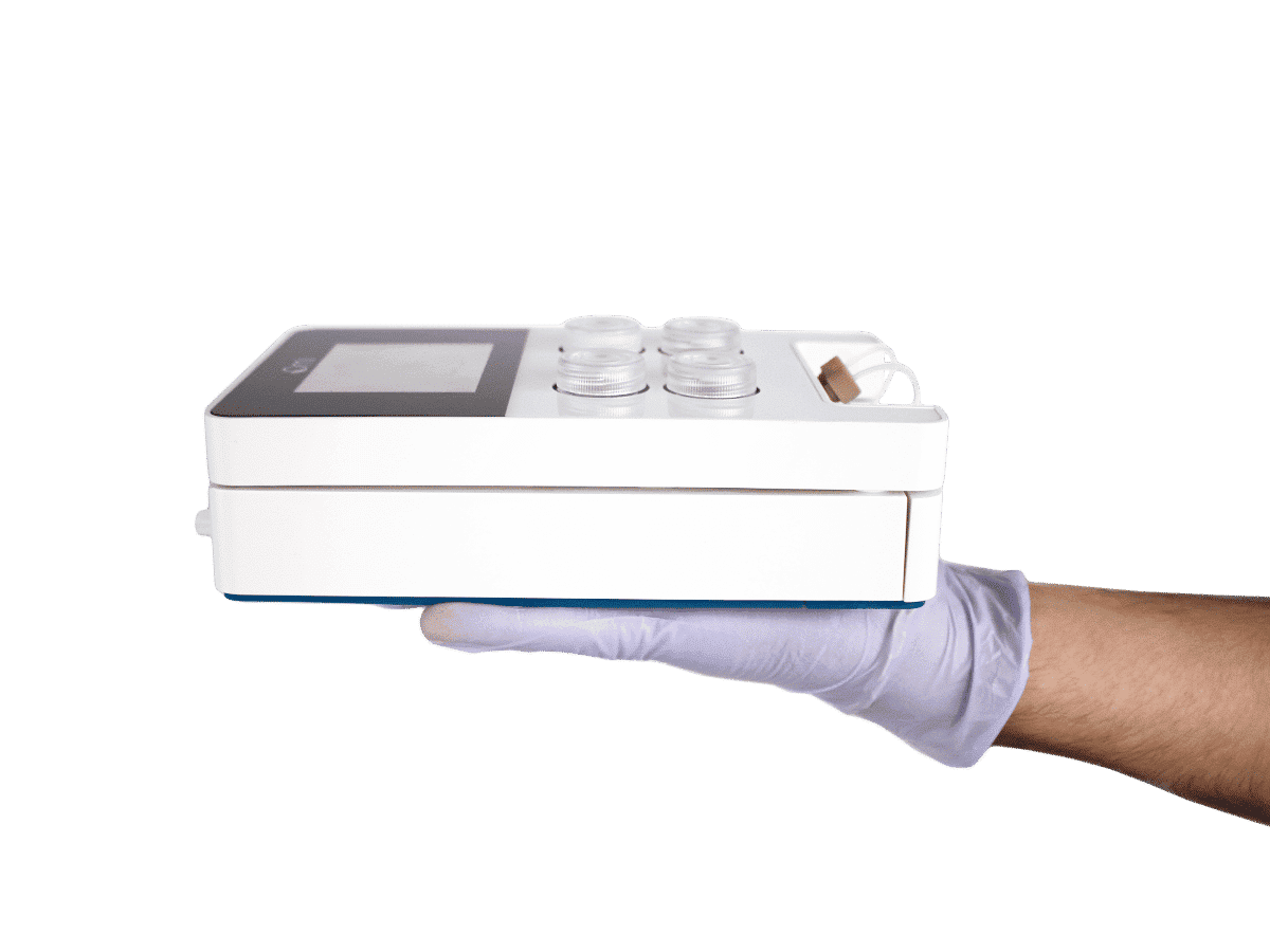
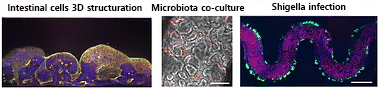
Figure 1: 3DP-μGut Model 3D structure, microbiota co-culture and shigella infection
*Delannoy E, Burette A, Janel S, Poiret S, Deboosere N, Daniel C, et al. Gut-on-chip methodology based on 3D-printed molds: a cost-effective and accessible approach. Lab Chip. 2025. doi: https://doi.org/10.1039/D5LC00147A
Gut-on-chip Design and Fabrication Approach
Flow modeling – a key parameter in chip design
The researchers designed a curved microchannel (750 µm × 750 µm × 11 mm) with computer-aided design (CAD) which mirrors anatomical curvature, enhancing physiological relevance (Fig 2). Molds for these channels were rapidly prototyped via desktop SLA 3D printing. The molds were cast in PDMS, top and bottom channels (with the PET membrane in-between) were bonded together, resulting in dual-channel chips.
This methodology emphasizes:
- Accessible fabrication suited to most biology labs
- Rapid iteration and batch design
- Methods to create thin layers of PDMS suitable for high-resolution live imaging
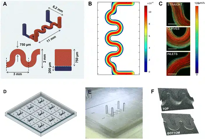
Figure 2: Illustration of the 3D printed mold. A) Schematical view of the microfluidic channels and dimensions. B) Simulated shear stress inside the chip geometry (in Pa). C) Measured velocities of fluorescent beads inside the microfluidic channel. D) CAD model of the 3DP-μGut mold E) close up photo of one of the printed patterns for a top channel mold. F) 3D reconstitution of the printed patterns imaged with a surfaced microscope.
To ensure physiological relevance, COMSOL Multiphysics was used to simulate flow within the curved channel.
- Laminar flow at ~60 µL/h — was found to be suitable to provide gentle shear stress and to preserve epithelial layers.
Simulations predicted uniform shear stress along the channel floor, with values in the range favorable for Caco-2 cell differentiation (typically <0.1 Pa for intestinal epithelium).
Perfusion and Flow Control
The 3DP-µGut was designed for compatibility with any perfusion system. In this study, the two Fluigent systems were compared:
- Flow EZ® Flow Controllers Set-up: for individual channel control modular system
- Omi OOAC Platform: Compact, automated, integrated platform adapted for biological use.
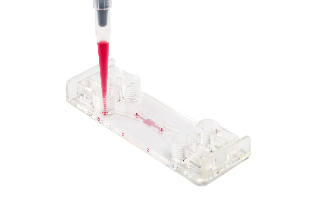
Both were connected via sterile tubing to culture medium reservoir, forming a closed-loop perfusion circuit for recirculation of media. As shown in Fig. 3, the Flow EZ set up provides a modular and adaptable system. The Omi is simpler to handle and set up with minimal tubing. The researcher used a Union connector in line to be able to disconnect the chip their convenience.
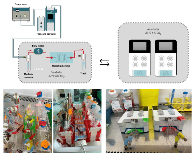
Figure 3: Flow EZ Perfusion Set-Up and Omi Platform with 3DP-µGut
Functional Impact of Controlled Perfusion in Gut-on-Chip Modelling
3D Epithelial Differentiation Mimicking In Vivo Tissue Architecture
Continuous perfusion in the 3DP-μGut had an impact on epithelial organization. Under flow rates of 60 µL/h by day 7, Caco-2 cells underwent polarization and formed dense monolayers with pronounced villus-like protrusions, closely resembling the three-dimensional microarchitecture of native intestinal epithelium (Fig 4).
Figure 4: Phase Contrast Imaging of Caco-2 Maturation 3DP-μGut maturation under flow conditions.. Top images: bar = 500 μm, bottom images: bar = 250 μm.
The shear stress generated by laminar flow acts as a physiological cue, promoting cytoskeletal remodeling and modulating gene expression patterns linked to differentiation. These findings demonstrate that the integration of controlled perfusion into the 3DP-μGut is beneficial for replicating the structural and functional complexity of the intestinal epithelium in vitro.
Confocal cross-sections revealed organized actin cytoskeletons along the apical surface (while perfused from basal side), tight junction proteins such as ZO-1 and adherents junction markers as E-cadherin formed continuous epithelial barriers (Fig.5). In contrast, static cultures displayed poorly developed junctional complexes and an overall flatter morphology.
Figure 5: Immunofluorescence Staining of Caco-2 cell inside 3DP-µGut A) top view, nucleus in blue (DAPI and actin in green, bar = 750 μm B) cross-section view, nucleus in blue (DAPI), tight junctions (ZO-1) in red and actin in green, bar = 100 μm
Culturing under Static vs Dynamic Conditions
When comparing the static 3DP-µGut system to perfused conditions, villus height measurements were significantly greater under perfusion than in the static model. No significant difference was observed between the Flow EZ setup and the Omi platform, as both systems use the same feedback mechanism to regulate flow rate. For perfusion and recirculation applications, the Omi and Flow EZ setups can be used interchangeably
Figure 6: Comparison of 3DP-µGut model under static and flow conditions A) and B) Immunofluorescence staining of the Caco-2 cells inside the 3DP-μGut devices under static or flow conditions A) top view, actin in yellow bar = 750 μm B) cross section view, nucleus in blue (DAPI), adherent junctions (E-cadherin) in red and actin in yellow, bar = 100 μm. C) Villi height measurement between static and flow conditions with Omi (automated flow system) and Flow EZ (stand-alone system).
Gut on chip modeling with microbial Co-culture and pathogen infection
The formation of a differentiated, three-dimensional (3D) intestinal epithelium within the 3DP-μGut was essential for stable co-culture with the human commensal strain L. plantarum NCIMB8826. In the 3D-differentiated system, L. plantarum achieved stable colonization over 24 hours (Fig. 7), while in poorly structured monolayers subjected to a flow, bacteria were progressively washed out (Fig. 7 C, D).
At the flow velocities measured in the chip, such bacterial loss is consistent with previously reported washout effects in flat environments. The villus-like topography increased the available surface area for bacterial adhesion and created protective low-shear niches, reducing the risk of bacterial detachment and enabling more persistent colonization.
Similarly, infection assays with Shigella flexneri revealed a significantly higher rate of bacterial adhesion and invasion in the 3D-structured epithelium compared to the flat monolayer configuration (Fig. 7B, E). Quantitative analysis demonstrated increased bacterial load and more extensive epithelial invasion in regions of low flow velocity within the 3D architecture. These results indicate that a biomimetic 3D structure not only supports stable colonization by commensals but also more accurately reproduces pathogenic invasion dynamics.
These findings highlight the importance of epithelial differentiation and 3D structuration in replicating physiologically relevant host–microbe interactions and maintaining a stable co-culture environment under continuous flow.
Figure 7: 3D μGut Model: Co-culture with L. plantarum (red) (A) and Infection with S. flexneri (green) (B) cale Bar = 1 mm (top), 500 μm (middle), 200 μm (bottom) C) L. plantarum count after retrieval from the 3DP-μGut. D) normalized L. plantarum density inside the 3DP-μGut over time E) Shigella flexneri bacterial area after infection
Conclusion and Future Directions
This gut on chip model methodology represents step forward to the accessibility of OOAC research and adopting cost-effective approach in biomedical research. It leverages technological advances with SLA 3D printing for rapid design and prototyping and precise flow-control technologies evolution for biology use. Dr Delannoy (2025) demonstrated the physiologically relevant epithelial maturation under flow, stable microbiological co-culture and pathogen infection. For future directions Delannoy et al. suggest several possible extensions:
- Integration with immune cells to model gut–immune interactions.
- Use of primary intestinal organoid-derived epithelium for patient-specific modeling.
- Addition of peristaltic motion using pneumatic actuation to mimic mechanical contractions.
- Real-time biosensing of TEER, oxygen, and pH for dynamic monitoring.
Such upgrades could turn the 3DP-μGut into a full-featured intestinal physiology platform capable of bridging fundamental research and preclinical testing.
Related Solutions

Related content
-
Expert Reviews: Basics of Microfluidics Optimizing Microfluidic Perfusion: Best Practices and Innovations Read more
-
Microfluidic Application Notes Controlling Flow Rate and Shear Stress with Omi™ to Study Endothelial Cell Response Read more
-
Microfluidic Application Notes Gut-on-Chip Model Development Using OOAC Platform, Omi Read more
-
Microfluidics Case Studies A multiplex microfluidic circuit for blood vessel-on-a-chip perfusion using Fluigent’s FlowEZ Read more
-
 Microfluidics White Papers A review of Organ on Chip Technology – A White Paper Read more
 -
Expert Reviews: Basics of Microfluidics Why Control Shear Stress in Cell Biology? Read more
-
Microfluidic Application Notes Development of a human gut-on-chip to assess the effect of shear stress on intestinal functions Read more