Passive and active mechanical stimulation in microfluidic systems
Organ-on-a-chip (OOC) technology has paved the way for investigating the impact of mechanical stimulation in cell biology research by reproducing key aspects of an in vivo cellular microenvironment.1 Combining microfluidics and microfabrication makes it possible to reproduce mechanical forces experienced by living tissues at the cell scale. Biomechanical stimulations experienced by cells fall into two categories:
- Active mechanical stimulation as a direct consequence of organ function. Organs like lungs, muscles and intestines are in active motion, and cells in those organs are mainly subjected to compression and stretching.
- Passive or indirect mechanical stimulation. Cells similar to conjunctive tissues or endothelial cells are passively exposed to the shear stress of blood or interstitial fluid. However, this type of stimulation still has a substantial effect on cell growth, phenotype and genetic expression.
Passive mechanical stimulation
Indirect mechanical forces – those that mainly originate from hydrodynamic phenomena – and the subsequent strain and shear stress are integral parts of the cellular microenvironment. Mechanical forces applied at the cell surface are translated into biochemical signals in cells. This phenomenon, called mechanotransduction, has been extensively described in the literature. It modulates cell proliferation, migration, phenotype, and/or differentiation1 and plays a critical role in tissue morphogenesis, homeostasis, and wound healing.2–4
As a result, reproducing these mechanical forces and subsequent shear stress and strain is critical to fully capturing the physiology of living tissues. Organs on chips are the perfect tools to implement shear stress, as one or several fluids can be perfused within the chip. Liquid flow usually induces shear stress on cells or tissues cultured on the device, and is called shear flow.1 Three types of flows encountered in vivo are typically generated for producing shear stress in an organ-on-a-chip devices: laminar, pulsatile and interstitial flow.
Shear flow in organ-on-a-chip systems
Shear from constant laminar flow
Laminar flow is predominant in tissues and organs, and therefore in organ-on-a-chip devices as well. The Reynolds number (for a tube Re = ρud / µ, with ρ the fluid density, u the flow velocity, and d the tube diameter) helps to predict flow patterns in different fluid flow situations. At low Reynolds number (typically Re < 1000), the flow is laminar: fluid flows in parallel layers, with no disruption between them, as opposed to turbulent flow. As the dimensions are at the micrometer scale in most tissues and organs (e. g., capillaries are about 8 to 10 microns in diameter), the Reynolds number is low (typically Re < 10). Flows are thus mainly laminar, with a characteristic velocity flow profile (figure 1). The shear stress is directly related to the flow velocity (see the next section for more information). As a result, laminar flow is a prerequisite in most organ-on-a-chip research, and particular care should be addressed to flow control.
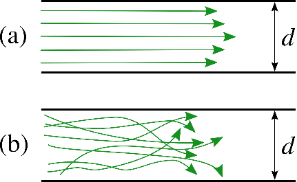
Figure 1: Schematic depiction of (a) laminar and (b) turbulent flow
D. Kamm et al. developed an in-vitro model of human microvasculature to study the effect of luminal flow (typically laminar) on the migration of tumoral cells, allowing for a better understanding of the process of metastatic cascade (extravasation and subsequent interstitial migration). In particular, they showed that luminal flow significantly promoted the extravasation potential of tumor cells compared to static conditions, with an average intravascular speed of tumor cells of ~ 12.5 μm/h under flow, compared to ~ 9.4 μm/h under static conditions. This result shows the important role of fluid flow during metastatic extravasation and invasion.5
For implementing flows, the type of perfusion system is critical. Peristaltic pumps are widely used but deliver a highly pulsatile flow that oscillates around the set flow rate value, which is not representative of any physiological condition in the body and can damage cells. Conversely, a pressure-based system can deliver constant flow. We demonstrated the importance of flow stability in vascular models by perfusing endothelial cells seeded in microfluidic chips using either a peristaltic pump or pressure-based flow controllers.
Shear from pulsatile flow
What is pulsatile flow?
Pulsatile flow is mainly observed in arteries. Pulsations are smoothed by the muscle of the arterial walls. Pulsations are a direct consequence of heartbeats. The heart acts as a reciprocating pump that drives blood directly into the aorta. At each stroke, the flow reaches a peak (systole), then diminishing to a low (diastole) until the next stroke.6 This produces pulsatile flow at each stroke instead of a continuous flow. Although pulsatile, flow remains laminar, with the velocity flow profile varying as a function of time.6 In fact, a typical flow rate curve of the artery for one heartbeat cycle displays two local maxima and a minimum, with positive and negative flow rate values (figure 2a).7
As a result, the flow direction and the amplitude of the velocity flow profile will vary as a function of time (figure 2b). Of course, this has an impact on the shear stress (or shear flow), since it is derived from flow velocity. More information on flow velocity patterns and subsequent shear flow can be found in the literature.6 Pulsatile flow is usually performed in blood vessel-on-chip models to simulate the actual pulsatile blood flow in human circulation.8
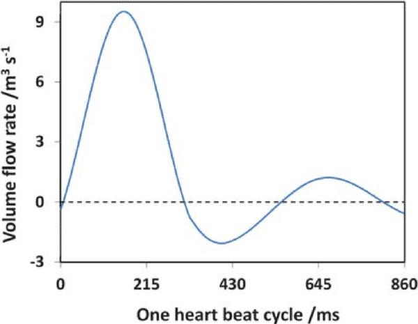
Figure 2: a) Flow rate as a function of time during a single heart beat cycle
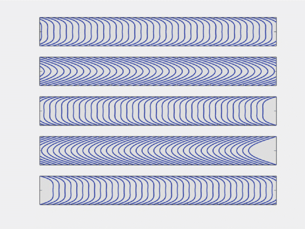
Figure 2: b) Example of an oscillatory velocity profiles in a rigid tube.6. Note that this is a mathematical simplification of oscillatory blood flow
As an example, microchannels mimicking human arteries and blood vessels were developed to investigate the influence of glucose and shear stress on endothelial cell apoptosis, a hallmark of vascular complications due to diabetes.8 The authors performed the experiments under pulsatile and static flow conditions. They observed that under static conditions, glucose-treated cells induced 5.5 times less apoptosis than when using pulsatile flow. This observation demonstrates the critical role of flow-induced shear stress in driving hyperglycemia-induced EC death.

Shear from interstitial fluid flow
What is interstitial fluid flow?
Interstitial fluid flow is the movement of fluid through the extracellular matrix of tissues, where cells such as fibroblasts, immune tissue cells, and adipocytes are found.1,9 Fluid flow carries large proteins through the interstitium and mechanically stimulates interstitial cells. Several studies have demonstrated that shear flow induced by interstitial fluid is crucial for cellular activities, as such flows induce physiological responses from cells10–14 such as cell differentiation. Interstitial fluid typically flows at a lower velocity compared to blood flow within vessels because of the high flow resistance of the extracellular matrix. Flow velocity profile and subsequent shear flow is also more difficult to define due to the complex architecture of the extracellular matrix, and because the fluid moves around the cell-matrix interface in all directions. Some studies have analyzed shear stress in such architectures in depth with numerical simulations.
A 3D cell culture microfluidic device was developed to provide new insight into how interstitial flow affects breast cancer cell invasion.15 Specifically, the authors found that compared to static flow conditions, interstitial flow increased the number of migratory cells, as well as their migratory speed. These observations demonstrate how important it is to consider interstitial flows in tumor models, as they affect tumor cell invasion and invasion direction.
Flow shear stress calculation in a microfluidic device
As explained in the above paragraphs, mechanical stimulation in the form of shear stress has a strong impact on cell behavior. The shear flow applied to adherent cells when performing organ-on-a-chip experiments can be determined using fluid dynamics equations, and more specifically, the continuity and Navier-Stokes equations. We present here the flow velocity profiles and shear stress equations for two common microfluidic channel geometries: circular and rectangular channels.
Circular channel
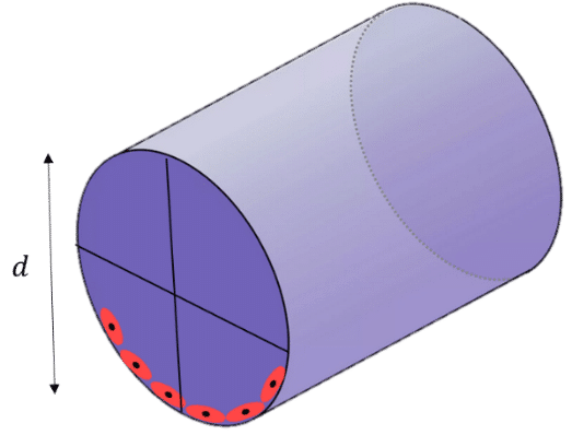
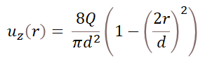
For a circular cross-section of diameter d, the fully developed velocity profile in cylindrical coordinates (r,θ,z) follows the equation:16
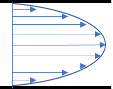
Where Q is the flow rate and r is the radial distance from the centerline of the channel (see figure). The distribution of flow velocities follows a parabolic profile, and the maximum velocity is for r = 0, at the center of the channel. It is of interest to determine the shear stress distribution at the channel wall (r = d/2), as this is where cells are located in the chip. To do so, the strain rate should be calculated by differentiating the flow velocity with respect to r. We get:
Where µ is the dynamic viscosity and Q is the flow rate. This indicates that the shear stress remains constant along the channel walls and is a function of the viscosity, flow rate, and channel diameter. At constant channel diameter and viscosity, the higher the flow rate, the higher the shear stress.
Rectangular channel
In microfluidic devices with rectangular channels, the flow velocity profile and subsequent shear stress are more complex. Wall shear stress is not constant and varies across the top, bottom, and side walls of the channel. Detailed analysis can be found in the literature.16 In some studies, however, the geometry is simplified by considering two infinite parallel plates instead of closed channels. Under this assumption, the shear stress follows the equation:
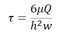
Where Q is the flow rate, µ is the dynamic viscosity, and w and h are the channel width and height, respectively.
Figure 4: Cross-section of a rectangular channel
Active mechanical stimulation
Compressive stress
Specific tissues such as heart, blood vessels, and bone cells are exposed to compression.17–19 An excellent example of the importance of compression is cartilage regeneration. It has been proven that mechanical stimulation of intervertebral disc cells (which mostly originates from compression) acts as an important stimulus for increasing cartilage matrix anabolism.
In vitro investigations have demonstrated that in the absence of physical stimulation, chondrocytes change their phenotype during proliferation and lose their capability to produce the typical extracellular matrix for cartilage.20
Mechanical stimulation is therefore a prerequisite for in-vitro investigations of cartilage and spinal diseases, and compression has well been studied in bone and cartilage tissue engineering.20,22
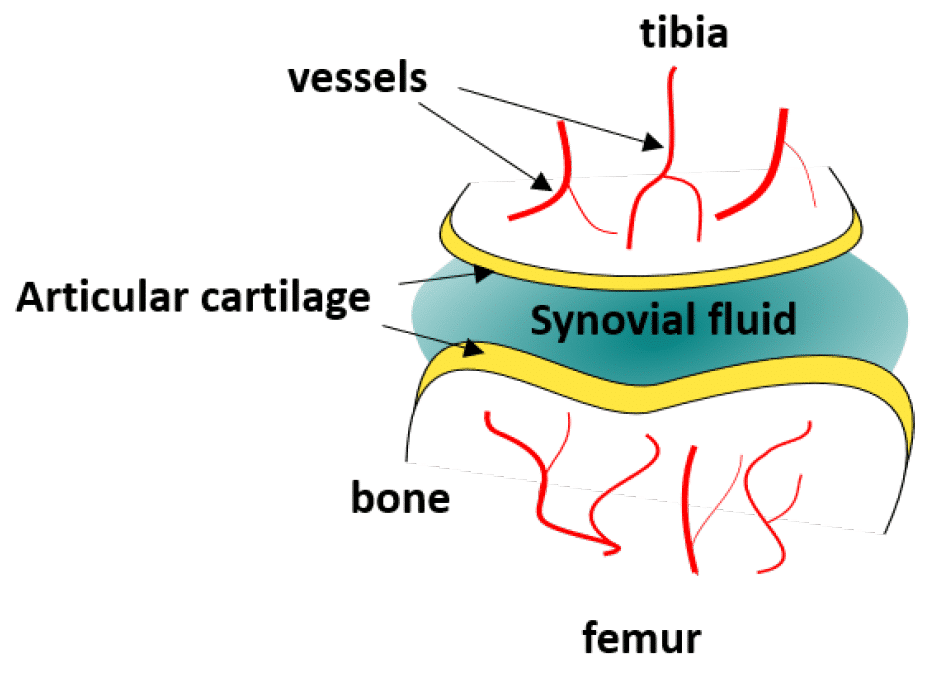
Figure 5: Schematic depiction of the knee joint
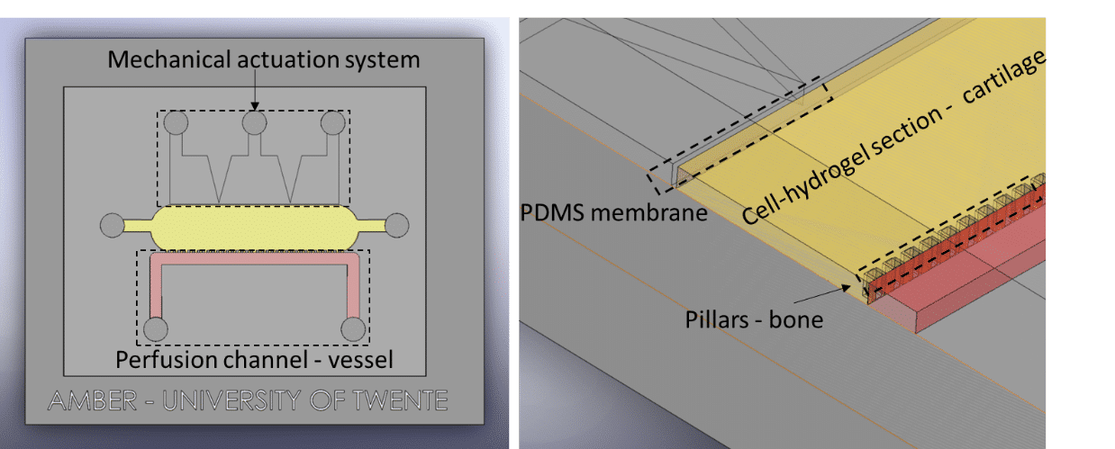
Fluigent presented a cartilage on a chip model (see figure) to elucidating how chondrocytes react to mechanical stimuli, allowing to understand processes triggering cartilage diseases like osteoarthritis11. This organ on a chip platform (consisting of a mechanical stimulation unit, a PDMS membrane, a 3D cell culture chamber, and a perfusion channel) allowed performing mechanical stimulation on cells, while creating dynamic culture conditions. More information can be found on the application note webpage.
Fluigent has presented a cartilage-on-a-chip model (see figure 5 a)) to elucidate how chondrocytes react to mechanical stimulation, allowing us to understand the processes that trigger cartilage diseases like osteoarthritis.27 This organ-on-a-chip platform (consisting of a mechanical stimulation unit, a PDMS membrane, a 3D cell culture chamber, and a perfusion channel) allowed researchers to apply mechanical stimulation to cells to create dynamic culture conditions.

In the microenvironment, compression imposed on a cell generally originates from cell-cell or cell-ECM interactions. Organ-on-a-chip devices can be used to mimic compression by applying pressure on specific areas of the chip, making it possible to compress cells or tissues in a precise manner. The devices usually integrate flexible membranes or diaphragms which bend upon compression.
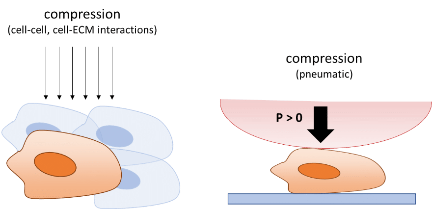
Membrane compression is mostly performed by applying air pressure on top of the membrane. Evaluating this mechanical force is easy, but determining the stress directly exerted on cells or tissues is more difficult, as the stress distribution will depend on the design of the organ-on-a-chip device.
Stress estimations are usually performed using finite element analysis and modeling to implement channel dimensions, material properties, and applied pressures.23,24
Several examples of compressive stress in organ-on-a-chip models can be found in the field of tissue engineering and regenerative medicine. A good example is the organ-on-a-chip model developed by Sim et al.25 Traditional methods like hydrostatic pressure chambers generally use a high amount of compression load,26 limiting the studies to high mechanical forces. In addition, such methods often require a large number of cells, samples, or fluid volumes. To address these limitations, an organ-on-a-chip device containing microscale cell culture chambers separated from an air-pressure chamber was developed, allowing researchers to apply micromechanical stimulations.25
The authors compared human mesenchymal stem cell proliferation using moderate levels of cyclic compressive stress (1 to 5 kPa) and at static conditions. They found that the cell proliferation rate of the mechanical stimulation group was about 1.5 higher than the control group after one week, revealing that cyclic compressive stress at moderate levels can enhance the proliferation of human mesenchymal stem cells.
Stretch and strain
Pulsatile flow is mainly observed in arteries. Pulsations are smoothed by the muscle of the arterial walls. Pulsations are a direct consequence of heartbeats. The heart acts as a reciprocating pump that drives blood directly into the aorta. At each stroke, the flow reaches a peak (systole), then diminishing to a low (diastole) until the next stroke.22 This produces pulsatile flow at each stroke instead of a continuous flow. Although pulsatile, flow remains laminar, with the velocity flow profile varying as a function of time22. In fact, a typical flow rate curve of the artery for one heartbeat cycle displays two local maxima and a minimum, with positive and negative flow rate values (figure 2a).23 As a result, the flow direction and the amplitude of the velocity flow profile will vary as a function of time (figure 2b). Of course, this has an impact on the shear stress (or shear flow), since it is derived from flow velocity. More information on flow velocity patterns and subsequent shear flow can be found in the literature.22 Pulsatile flow is usually performed in blood vessel-on-chip models to simulate the actual pulsatile blood flow in human circulation.24
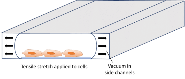
In addition to flow-induced shear stress and compressive stress, tensile mechanical force applied to the cellular microenvironment leads to strain and stress on the tissue. The lung is a good example of this phenomenon. During inspiration, intrapleural pressure decreases, causing the alveoli to expand. This pulls air into the lungs, resulting in stretching of the alveolar epithelium and the endothelium in adjacent capillaries.28 This stretching results in mechanical strains induced on cells. It has already been demonstrated that tensile stress induced by stretching affects cellular membrane integrity29 and cell shape, spreading, and proliferation.30 Stretching is usually performed for gut-on-a-chip, heart-on-a-chip or muscle-on-a-chip models, as these organs are subject to stretching or strain in vivo.29–31 Stretching in organ-on-a-chip devices is usually performed using pressure or vacuum.29,32–36 The chips usually consist of a central channel for cell culture and perfusion, with pressurized side channels below or around the central channel (see figure). The channels are made of flexible material, allowing for elastic distortion of the membrane when applying positive or negative pressure. Upon bending, cells or tissues are stretched and experience a tensile stress.

It is possible to estimate the strain and stress applied to the device and cells using theoretical models derived from continuum mechanics that are computed in finite element models. These models are relatively complex and can differ from one system to another (bi-axial or circumferential strain, gel or cell culture, etc.). Excellent model descriptions and derivations can be found in the literature.29,33,34,36–39 Briefly, the authors used nonlinear or hyperelastic material models that connect stresses to strains, using tensors such as the Cauchy-Green strain tensor and the Piola-Kirchhoff stress tensor. The models are generally implemented in finite element software models for validation.
A great example of how organ on a chip technology with stretch-induced cell stress has led to scientific progress is the gut-on-a-chip model developed by a joint group of researchers from Harvard University and MIT. Human intestinal inflammatory diseases such as Crohn’s disease are thought to be caused by a combination of many factors such as complex interactions between gut microbiome,40 intestinal mucosa,41 and peristalsis suppression41 (strongly associated with inflammation and intestinal bacterial overgrowth). However, it is not possible to study the intrinsic effect of each factor in vivo as they are inextricably linked. Traditional and in-vitro models (i.e. cell culture in flasks or petri dishes) are also incompatible with such studies as they poorly reproduce the pathophysiology of human inflammatory bowel disease. In such models, the peristaltic motion that acts as a strong driver of normal cell differentiation is missing. To address these limitations, Kim et al. developed a human gut-on-a-chip device consisting of two microfluidic channels separated by a porous flexible membrane coated with extracellular matrix, and two side vacuum chambers for simulating peristaltic motions and subsequent cell stretching.31 The devices allowed them to study the factors of intestinal inflammatory diseases individually. They used the chip to analyze the effect of cyclic stretching (10% in cell strain, 0.15 Hz in frequency) on the proliferation of GFPEC bacteria cultured under flow. They observed that bacterial cell densities more than doubled within a day when cultured without cyclic stretching.
This discovery suggested that cessation of epithelial distortion can trigger bacterial overgrowth, and refuted the previous hypothesis that bacterial overgrowth originated from fluid flow.42 This new organ-on-a-chip model made it possible to analyze multiple factors in a controlled manner, which was not possible using existing in-vitro systems or animal models, allowing researchers to gain new insights into gut pathophysiology.