The Raydrop: A new droplet generation device based on non‑embedded co-flow‑focusing
In an article recently published in Scientific Reports, Adrien Dewandre et al. describe the Raydrop: a microfluidic droplet generator based on non-embedded co-flow-focusing. After introducing the device, they demonstrate that this new configuration offers the ability to emulsify any liquid with a wide range of droplet sizes. This universality is demonstrated with experimental results. Modeling is also performed, supporting experimental results, and allowing for the prediction of droplet size and production regime (dripping, jetting regimes).
A new configuration to fill the gap in the design of microfluidic droplet generators
In recent years, droplet microfluidics has become an important tool for many different applications, including fundamental studies on emulsification, crystallization, chemical reaction, molecular encapsulation, particle synthesis, digital PCR, or single-cell analysis.
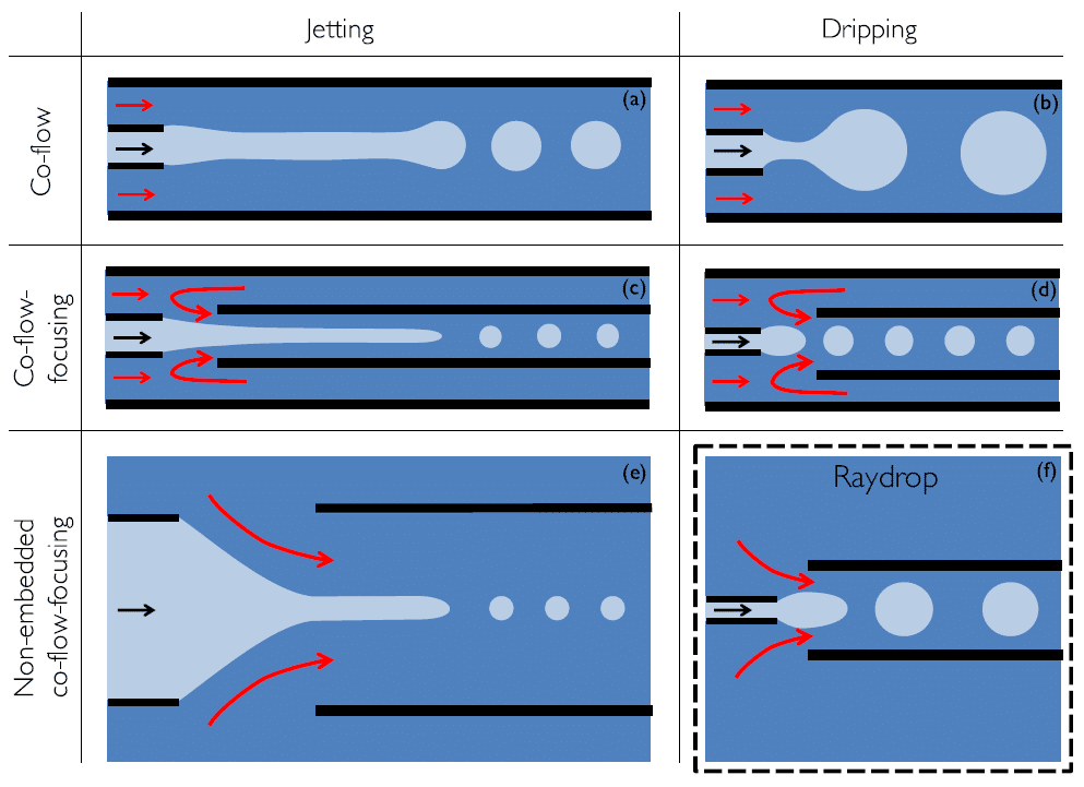
Most commercial microfluidic droplet generators rely on the planar flow‑focusing configuration implemented in polymer or glass chips. This geometry has many limitations, such as the need for specific coatings, or the use of dedicated surfactants. Conversely, glass capillary‑based droplet generators are a great improvement, as the dispersed phase is never in contact with the walls of the outer capillary (figure 1 a,b).
They have been difficult to implement (centering of the capillary), and commercially-available designs have shown poor flexibility for droplet production (> 100 µm diameter, < 1 kHz generation rate). Centering can be simplified by inserting two circular capillaries into a square outer flow capillary (figure 1 c,d), but the related manufacturing methods limit large scale production, and high throughput droplet production is still not achieved.A new configuration offers a promising alternative by placing the extraction tube without any surrounding confinement in front of the injection tube (see Fig. 1e). However, this system exclusively works in the jetting regime, which does not guarantee droplet monodispersity associated to the dripping regime.
The authors present the Raydrop: a new system based on the latter configuration, but in which the dripping regime is enforced by using an injection capillary of diameter smaller than the extraction one (figure 1f). This is achieved with an improved combination of cutting-edge machining and 3D printing techniques. This non-embedded design presents both the characteristics of a co-flow and a flow-focusing, and is called non-embedded co-flow-focusing. This configuration fills the gap in the design array of microfluidic droplet generators.
The Raydrop is an easy to use commercially available microfluidic chip for droplet generation, with outstanding monodisperse production.
The Raydrop: a device based on the alignment of two capillaries immersed in a pressurized chamber
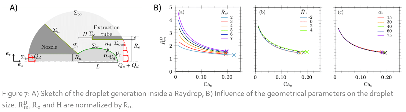
The Raydrop consists of a metallic pressurized chamber filled with a continuous phase. Two inserts supporting the glass capillaries (injection and extraction capillaries) are introduced on the lateral sides so that the capillaries are perfectly aligned and almost in contact at the center of the chamber. The dispersed phase flows from the injection capillary, and meets the continuous phase at the intersection to the extraction capillary (see figure 2). Droplets are generated and flow through the extraction capillary. The 3D-printed micro-nozzle connected at the tip of the injection capillary (see figure 2 d) enforces the dripping regime of droplet formation.
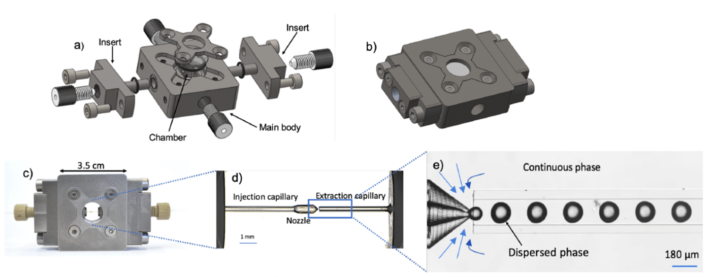
The capillaries are held into the inserts so that alignment is guaranteed for all combinations, and a fixed gap between the nozzle and the extraction capillary is maintained. Two glass windows on the top and bottom faces of the device seal the chamber and allow for the observation of the droplets.
The technological breakthrough of this design is two-fold:
- It enables the high-throughput generation of monodisperse droplets, intrinsic to the dripping regime, for a wide variety of fluids.
- It benefits from specific fabrication techniques and materials compatible with large-scale production of the device.
Additionally, the device is made plug-and-play thanks to the standard connections and the possibility to assemble and disassemble all parts for cleaning easily.
Droplet generation using the raydrop
Once columns are formed within the microfluidic chip, the solution containing MDA-MB-231 cells was subsequently injected. We can observe in the figure on the left below cells that bind to the EpCAM coated columns, exhibiting green, blue, and orange fluorescence. Note that the columns formed by the magnetic beads display a weak orange fluorescence, as Phalloidin binds to EpCAM. The figure on the right shows a composite micrograph of cells attached to a column using higher magnification. We can distinctly observe orange fluorescence indicating stained actin filaments, blue fluorescence indicating stained nucleus, and green fluorescence indicating damaged DNA within the nucleus. These results confirm the proper function of the staining injection protocol.
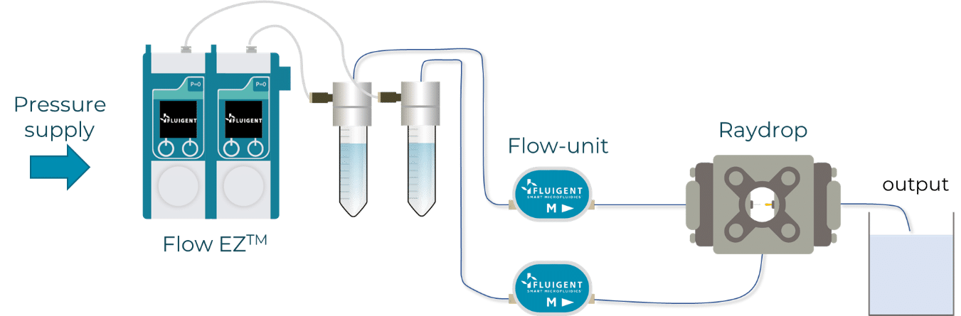
Using the Fluigent Flow-EZ or MFCS-EZ pressure pumps, fluids are injected within the inner capillary (dispersed phase) and the chamber (continuous phase). Flow rates are measured using Flow Units. Different glass capillary geometries can be used and interchanged depending on the required droplet size and frequency. These geometries are referred as “couples”. Here, two couples were used. Couple 1 consists of a nozzle of 30 µm diameter and a 150 µm diameter extraction capillary, couple 2 with a nozzle of 90 µm diameter and a 450 µm diameter extraction capillary. Qc and Qd are respectively defined as the flow rate of the continuous and dispersed phase.
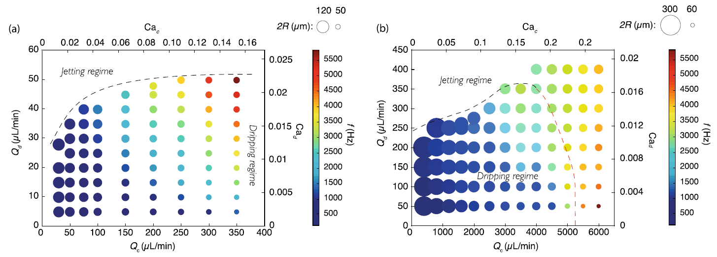
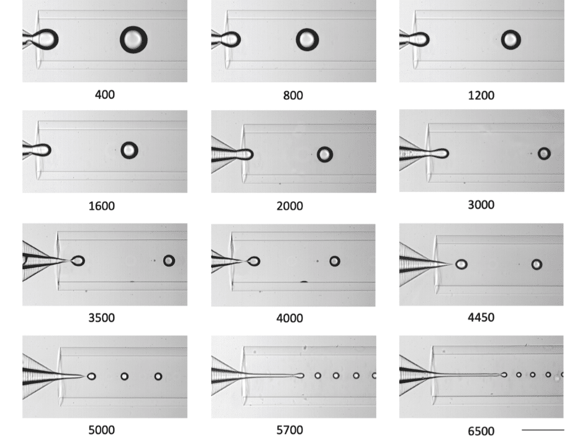
Figure 4 shows water in mineral oil emulsions with droplet diameter and frequencies reached when using two different couples. The jetting-dripping regimes are also displayed. Using couple 1 (figure 4 (a)), droplet with radius R ranging from 25 to 60 µm are produced, with frequencies ranging from 500 to 5 000 Hz, at high monodispersity: the coefficient of variation (CV) is lower than 1%. Also, the dripping-jetting transition reaches a plateau for Qc = 200 μL/min (figure 4 (a)), indicating that the dripping-jetting transition is only determined by the geometry in this region.
Using couple 2, droplets with radius R ranging from 60 to 300 µm are generated, with frequencies ranging from 500 to 5 000 Hz. Two dripping-jetting transitions can be observed, as this couple allows for reaching higher flow rates values. A transition is observed when increasing Qd (black dashed line in Fig. 3b), and another transition when Qc is increased above a threshold value (red dashed line in Fig. 3b).
Interestingly, this second transition at high Qc separates a monodisperse regime with CV < 1 % from a polydisperse regime with CV > 4 % (a value still much smaller than typical CV values observed in the jetting regime, usually larger than 10%). This transition is illustrated in figure 4 b), where Qd is kept constant while Qc is increased. Note that no polydisperse regime seems to be reached whatever the value of Qc.
A theoretical model to predict droplet size and generation regime
The authors make use of continuum and fluid mechanics to make a highly sophisticated model. The details can be found in the paper. This system of equations is solved using the finite element method (FEM). This model is first validated by comparing with experimental data, as shown in figure 6 (Cac is the capillary number of the continuous phase). It has next been used to study the effect of several parameters such as fluid viscosity, inertia, and geometrical parameters (nozzle inclination angle, nozzle-capillary distance …) on droplet formation.
Using this model and quasi-static simulations (Qd << Qc) it is possible to predict droplet size as a function of several geometrical parameters. Figure 7 shows the effect of (a) the extraction capillary radius, (b) the nozzle-capillary distance and (c) the nozzle inclination on droplet size. This model is thus a great tool for end users, as it allows to find an appropriate set of parameters for a targeted droplet size and generation regime.
Raydrop versatility
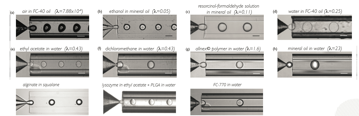
Using the Raydrop, it is also possible to generate bubbles and droplets involving a wide variety of fluid pairs. This universality is demonstrated in figure 8, where the Raydrop was used to generate air-in-oil, ethanol-in-oil, water-in-oil, allnex© polymer-in-water, or oil-in-water… while keeping its versatility in droplet size and frequency.
Conclusion
The authors demonstrated several advantages of the Raydrop including:
- high monodispersity ensured by the dripping regime,
- robustness of the fabrication technique,
- optimization capabilities based on numerical modelling,
- and the universality of the configuration.