微流控的工作原理是什么?
微流控需要非常精确的流体控制,同时使用较小的体积和空间。微流控芯片是微流控研究中所使用的设备,其中的微通道已经过模制或图案化设计。微通道相互连通,支持流体流经不同的通道,从一个位置流动到另一个位置。该网络通过进口和出口连接到外部环境。使用被动方式或外部主动系统(压力控制器、注射泵或蠕动泵)、管理或从微流控芯片中去除流体或气体。
通道可能具有不同的内径(通常范围为5到500 μm),并且其网络必须针对要进行的应用和分析进行专门设计。因此,微流控芯片支持在单个微型设备中集成多种功能,这些功能通常需要整个实验室才能实现。
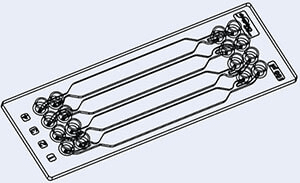
微流控芯片示例
流体在微米尺度下会发生哪些变化?
在微米尺度下,流体的行为会发生变化并呈现多个优点:快速导热、增加表面体积比、层流和可能的扩散混合。此外,微流控可显著减少样本和试剂消耗、缩短实验时间并降低应用的总体成本。
得益于微电子学的发展和晶体管的微型化,这一概念被引入生物医学和化学领域,并推出了“芯片实验室”(LoC)原理和“微型全分析系统”(μTAS)。1979年,S.Terry等人开发出一种硅基芯片,实现了气相色谱仪功能的微型化,这是微流控芯片的早期示例。 自这一开创性产品问世以来,微流控技术经历了爆炸式的增长,成为学术研究人员和工业集团不可或缺的工具。

微流控技术的发展
微流控技术有哪些优点?
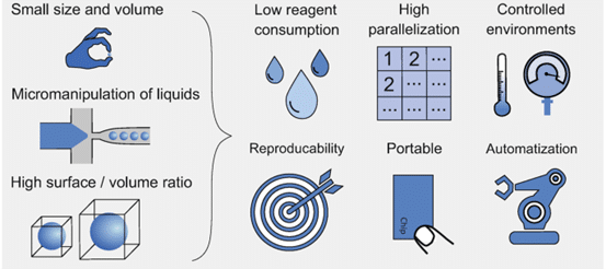
微流控技术的优点 [1]
微流控技术的关键概念是将通常需要整个实验室才能完成的操作整合到一个简单的微型系统中。目前,得益于设备的紧凑尺寸,微流控系统以复用技术取代了传统的放大技术,这显著缩短了从配方到生产所需的时间。因此,微流控技术不仅可用于分析目的,还可用于过程工业的大规模生产,特别是精细化工、食品、环境和制药业。近年来,微流控设备也作为分析工具广泛应用于生物化学和分子生物学应用领域。
微流控系统还提供卓越的数据质量和改进的参数控制,在保持性能的同时,实现过程自动化。该系统只需少量样本操作,即可对样本进行处理和分析。微流控芯片与流体处理系统的结合经过精心设计,并加入自动化技术,即使用户专业知识水平不高也能生成多步反应,,且具备多种功能。
例如,与传统方法相比,微流控技术提高了水分析的灵敏度,能够检测出较低浓度的污染物。分析时间大幅缩短,可以进行实时监测并提高效率,同时使用少量样本以防止水浪费。
此外,由于微流控技术能够满足高质量且受到严格监管的医疗产品的需求,因此预计该技术将在未来的纳米医药生产、治疗产品给药及诊断中发挥重要作用。
如何发挥微流控技术的这些优势。
在微流控技术中,若想成功执行微流控实验,掌握各种微米尺度的流量控制技术变得愈加重要。要生成可靠且可再现的数据,需要精确控制流量参数:例如,系统中应用的流速将定义产生的液滴尺寸,或对细胞产生特定的剪切应力,从而影响其生长、空间组织和蛋白分泌。应用于系统的流速误差会导致出现多分散液滴、系统不稳定、细胞受损,甚至造成实验失败。因此,全面可靠的流量控制对于任何微流控系统都至关重要。
微流控中用于输送流体的最常用系统是什么?
注射泵
注射泵适合小剂量注射,但其精度不如压力泵,特别是在非常低的流速下,精度更低。市面上的产品质量各异,价格不一。
在微流控流量控制装置中,注射泵基于由步进电机驱动的机械系统,该系统以精确的速率推动注射器,具有较宽的流速范围。但是,机械驱动会产生流量脉动,并且响应时间和沉淀时间较长,特别是在存在气泡、黏性流体和柔性管路的情况下。此外,系统内的实际流速不受监控,如果由于泄漏、堵塞或不正确的设置而未达到流速命令,则可能产生结果偏差。压力也不受控制,如果微系统堵塞,压力就会上升到会造成损坏的水平。文本建议用户定期检查堵塞情况,特别是在使用微粒时,并在自动化实验时了解该技术的潜在限制。
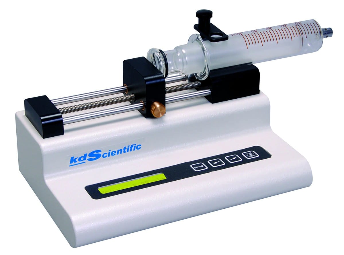
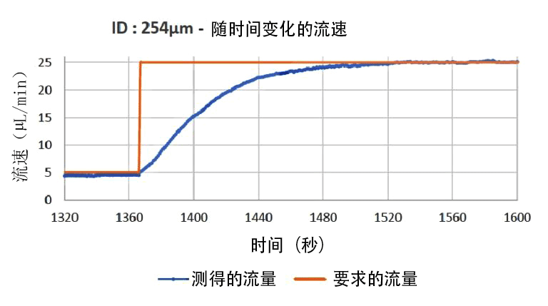
注射泵响应时间图
蠕动泵
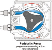
蠕动泵送过程基于软管的压缩和放松。旋转滚轮沿着安装在泵内的管路滚动并压缩管路,在其中形成真空并吸取流体。 这种流体驱动方法可用于微流控实验室且相当经济实惠。
在微流控流量控制装置中,蠕动泵选件非常适合大流量和高流速,也适用于流体再循环。但是,压缩管道会引起流动脉冲,这不适合大多数微流控应用,这类应用的流量精度至关重要。 此外,应定期更换软管,防止软管损坏。
压力控制器解决方案
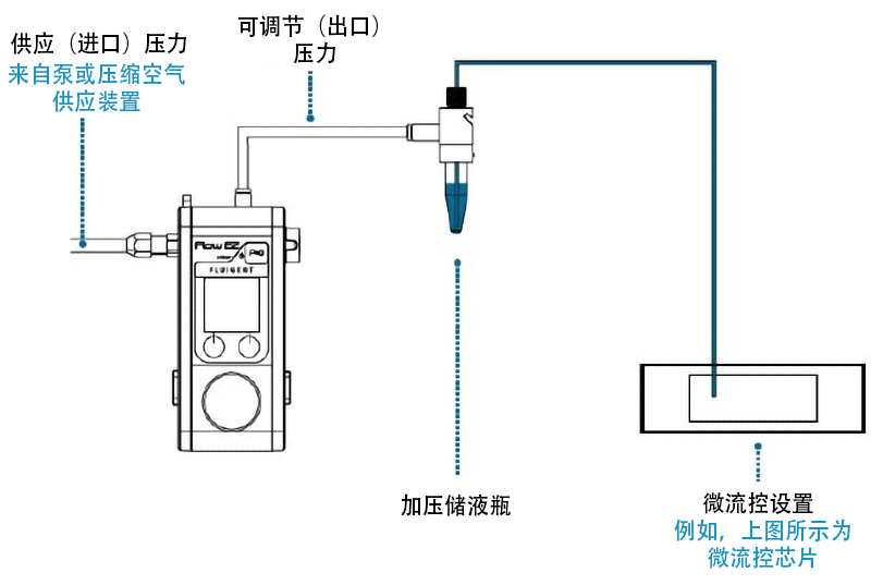
压力驱动式流量控制器的流体驱动方法包括对装有样本的储液瓶进行加压,然后将其快速注入微流控设备中。这种储液瓶的尺寸多种多样,选择范围涵盖1.5/2ml的Eppendorf管到15/50ml的Falcon小瓶,甚至有几百毫升的大瓶。
为了实现微流控流量控制,受控气体压力会推动流体,然后流体经储液瓶出口流出。由于气压控制器具有出色的调节功能,这些系统可以实现从亚纳升/分钟到几十毫升/分钟的高度稳定的流速。

Fluigent的MFCS和FLOW EZ压力控制器
Fluigent具有MFCS-EZ™和LineUp™压力驱动式控制器,其分辨率低至7×10⁻³ bar。例如,我们所有系列产品的稳定时间最低为100ms,分辨率为满量程(压力传感器分辨率)的0.03%,测量值的稳定性变异系数为0.1%。
如果流量传感器已与压力控制器连接,则用户可以直接控制流速。将通过强大的算法(例如Fluigent OxyGEN)对压力进行调节。此外,通过与压力控制器连接的阀可以实现流体再循环。
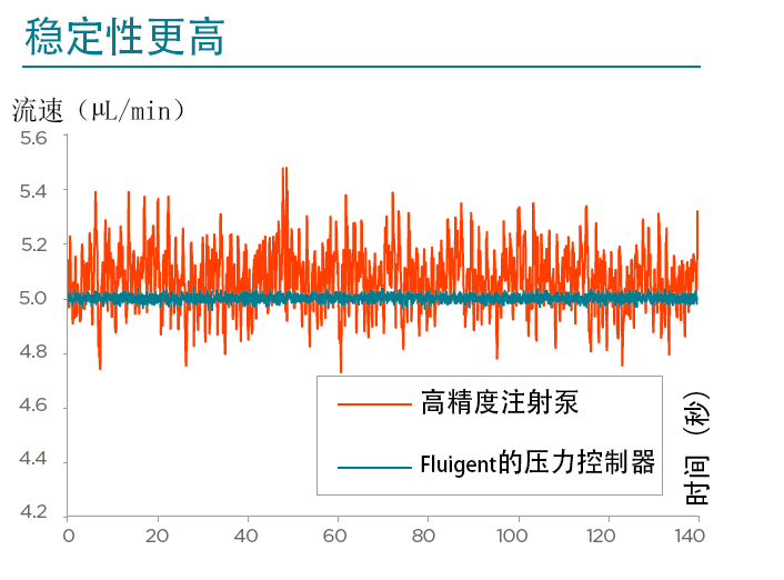
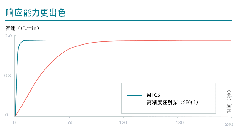
压力泵的另一个优点是用户只用一个压力通道即可对多个储液瓶加压。如果您想按顺序注射不同的溶液,这可以显著降低设置成本。凭借这些优点,我们的压力式流量控制器适用于对参数(尺寸、混合、流速等)的控制和精度要求较高的应用。并在与液滴生成、ddPCR、细胞培养和细胞灌注、器官芯片研究以及纳米粒、微胶囊和微珠合成相关的实验中提供了出色的结果。
Reference
1- Bahnemann, J.; Grünberge, A. Microfluidics in Biotechnology: Overview and Status Quo. Advances in Biochemical Engineering/Biotechnology book series, 2022, ABE,volume 179.